5.2. GENERAL CONFIGURATION
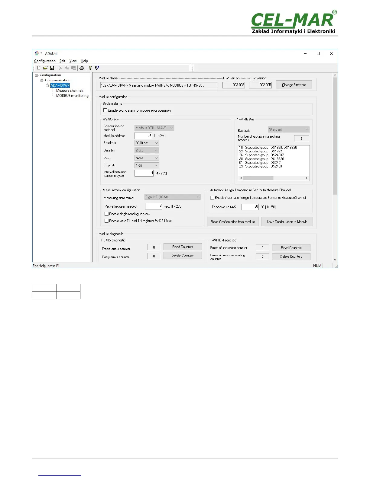
Fig 7. View of general configuration ADAUtil window
Main configuration is started by setting SW1 micro switch in configuration mode as follows:
SW1-1 SW1-2
ON OFF
Yellow LED will blink with frequency 1 Hz.
Run ADAUtil software and select branch Configuration=>Communication on left panel and on right select COM port used for
module configuration. Then select branch Configuration=>Communication=>ADA-401WP on left panel and on right press [Read
Configuration form Module]. Set the parameters in the following sections.
5.2.1. SYSTEM ALARMS
Section System Alarms has option:
Enabling sound alarm for module error operation – enable or disable (disable - manufacturer setting).
Errors that are signalled by short sound:
– errors of sensors searching,
– errors of reading temperature from sensors,
– errors in RS485 communication,
– errors of CRC sensors serial number,
– short circuit on 1-WIRE bus,
– no sensor,
– no 1-WIRE bus controller.
5.2.2. RS485 CONFIGURATION
Section RS485 bus has options:
– Communication Protocol - allows choice of protocol (at the moment available - MODBUS RTU-SLAVE)),
– Module address – setting module address for selected protocol from range 1 to 247 (64 - manufacturer setting),
– Baud rate: 300bps – 230400bps (9600bps – factory default),
– Data bits number: 8 bits (readout only),
– Parity control: none, even parity, different parity, (non – factory default),
– Stop bits number: 1-bit or 2-bits (1-Bit – factory default),
– Interval between frames in bytes: 4 – 255, for MODBUS RTU protocol 4-character – factory default.
10