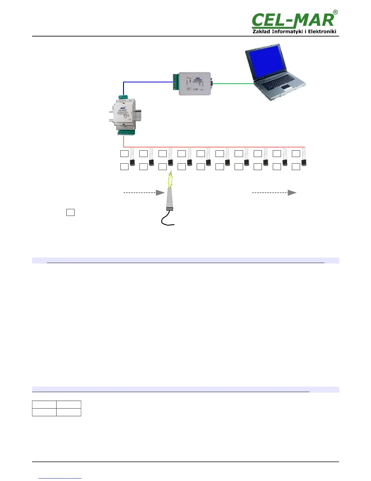
Fig 9. Visualization of I Automatic Assign Temperature Sensor to Measure Channel
5.3.3. SENSORS REMOVING
Double click on the field Sensor SN of channel, and press the Delete key of a keyboard and go to next field. Save the configuration to
module memory by pressing button Save Configuration to Module.
To the module memory will be saved only configuration of measuring channels which fields were marked in ping.
5.3.4. MEASUREMENT CHANNEL PARAMETERS CONFIGURATION
After ended adding and changing sensors order, can be configured other parameters of measuring channels. Successively fill in fields:
Location – enter a location of installed sensors, maximum 9 characters.
Val.Lo – value of lower limit measure value. If the value measured by sensor will be lower, that will be setted the byte of exceed lower
threshold V<VL in the register of measurement channel.
Val.Hi – value of high limit measure value. If the value measured by sensor will be higher, that will be setted the byte of exceed upper
threshold V>VL in the register of measurement channel.
Offset – The value of which will be increased or decreased the value measured by the sensor measurement to a linear calibration
measurement. The offset depends on the type of sensor:
- from -1.27°C to +1.27°C for digital temperature sensors DTS-RJ45, DTS-103, DTS-107, DES-300-T, DES-300E-T,
- from -12.70%Hig to +12.70%Hig for digital relative humidity sensors: DES-216-H, DES-300-H etc.,
- from -12.70hPa to +12.70hPa for digital atmospheric pressure sensors: DES-216-AP, DES-300-AP etc.
Enable – activation this field will cues actualisation of measurement and status for channel, deactivation will cues block actualisation.
Assigned - activation this field will cues adding a sensor to the Channel. Deactivation will cues that in case of next sensors searching
by the module in field [Sensor SN] channel can be serial number or other sensor.
Each proper changing of the list's field of table Measuring Channel Configuration is causing highlighting of data of the measuring
channel to the ping color.
Save the configuration to module memory by pressing button Save Configuration to Module.
To the module memory will be saved only configuration of measuring channels which fields were marked in ping.
Set the SW1 switch section to run mode as in the table below.
SW1-1 SW1-2
OFF OFF
Yellow LED will be OFF.
5.4. SAVING TO FILE
Main configuration and measurement channel configuration can be saved to a configuration file. It lets to save the configuration of
each measuring module of the system. Choose from menu Configuration => Save or Save As, and a window Save As will open
(fig.10). Enter the file name in the field File Name and press button Save.
14