Example. 2 channels status readout (address 40201 to 40202 / address 30201 to 30202)
01-03-00-C9-00-02-CRCLo-CRCHi
01-04-00-C9-00-02-CRCLo-CRCHi
Response
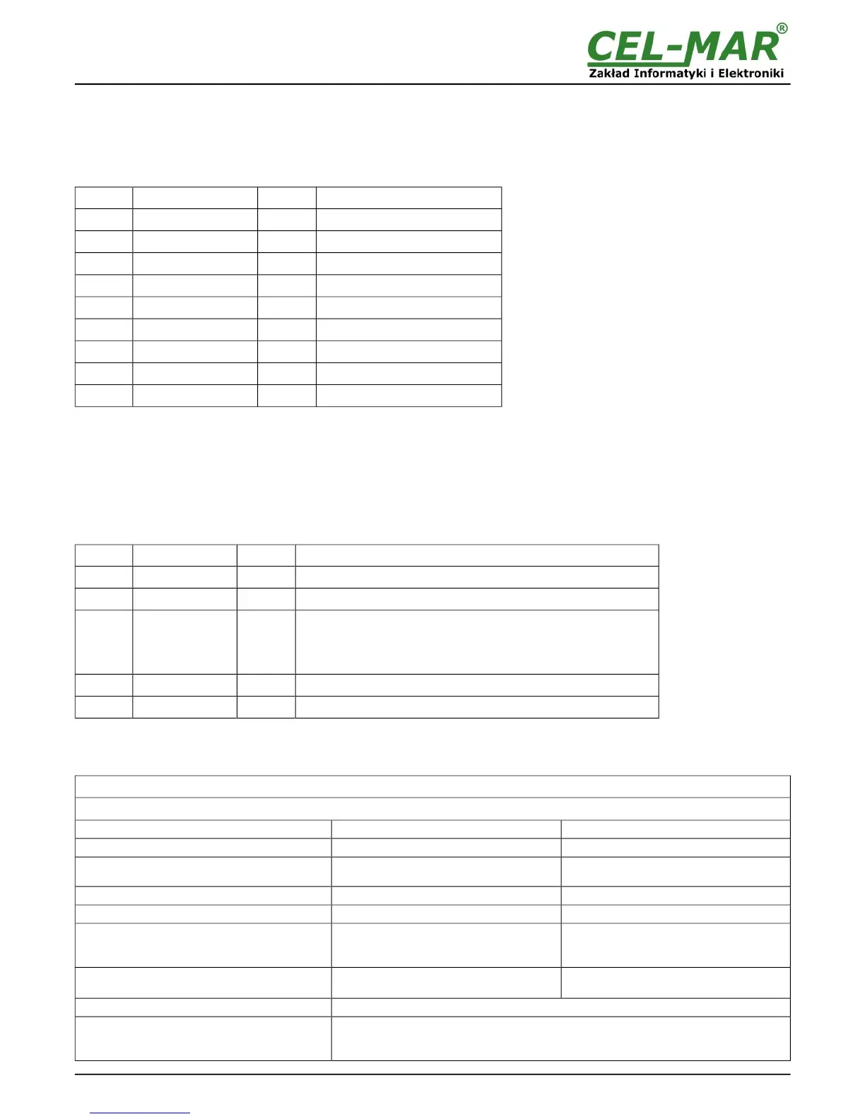
Byte no Designation Size Value [hex]
00 Module address 1-byte
01 [01 to F7]
01 Function code 1-byte
03 / 04
02 Number of data bytes N-byte
04 [depend on inquiry (4)]
03 Status 1-Hi 1-byte
00
04 Status 1-Lo 1-byte
01
05 Status 2-Hi 1-byte
00
06 Status 2-Lo 1-byte
02
07 CRC - Lo 1-byte
---
08 CRC - Hi 1-byte
---
Example. 2 channels status readout (address 40201 to 40202 / address 30201 to 30202)
01-03-04-00-01-00-02-CRCLo-CRCHi
01-04-04-00-01-00-02-CRCLo-CRCHi
In respond channel status 0 to 1 is present as 4-byte with value:
- channel_0 hi = 00, lo = 01 – sensor during converting
- channel_1 hi = 00, lo = 02 – detection of sensor
Response - in case of error
Byte no Designation Size Value [hex]
00 Module address 1-byte
01 [1 to F7]
01 Function code 1-byte
83 / 84
02 Error code 1-byte
01 - unknown function
02 - unknown data address
03 - unknown data value
04 - unknown error while inquiry converting
03 CRC - Lo 1-byte
04 CRC - Hi 1-byte
8. SPECIFICATION
TECHNICAL DATA
Transmission Parameters
Interface RS-485 1-WIRE
Connector Screw terminal, wire max. Ø 2,5mm
2
. Screw terminal, wire max. Ø 2,5mm
2
.
Line length
1200 m
Up to 300 m
depends on 1-Wire bus and used cables
Maximum number of connected device 32 devices 64 sensors
Maximum baud rate
Up to 230,4 kbps standard: up to 16,3 kbps,
Transmission line
2-pair twisted cable eg UTP
4x2x0,5(24AWG), shield inside large
interferences eg STP 4x2x0,5(24AWG)
1-pair, 2-pair twisted cable eg UTP
4x2x0,5(24AWG), shield inside large
interferences eg STP 4x2x0,5(24AWG)
Transmission type
RS485/RS422 MODBUS - halfduplex
(inquiry - response)
fullduplex (sending and receiving on the
same wire)
Standards
1-WIRE, EIA-485, CCITT V.11.
Optical Signalization
• PWR – green LED power supply,
• RX - red LED data receiving through 1-WIRE interface,
• TX - yellow LED data transmission through 1-WIRE interface
27