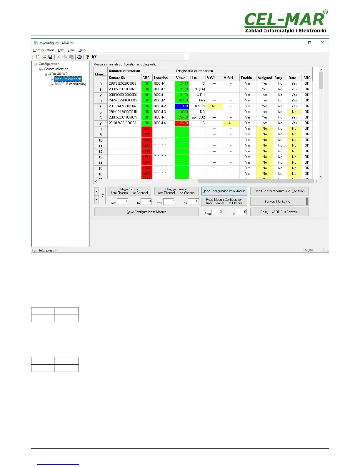
Fig 13.View of ADAUtil measuring channel diagnostic window
Readout of channels diagnostic and sensor measurement values by pressing the button Read Sensor Measure and Condition.
Continuous monitoring of measurement channels diagnostic and measuring value from sensors by pressing the button Sensors
Monitoring.
Normal operating of 1-WIRE network :
- no corruption of CRC,
- all connected sensors are detected,
- no readout error temperature.
After that, can be set the switch section SW1 to RUN mode as in the table below.
SW1-1 SW1-2
OFF OFF
Yellow LED will be OFF.
6.3. DIAGNOSTIC OF MODBUS PROTOCOL
After finishing diagnostic of measurement channels of each ADA-401WP module in installation, can be started diagnostic and
checking of correctness MODBUS protocol communication on RS485 bus. The module should be in the RUN mode – the SW1 micro
switch should be setted like in the table below.
SW1-1 SW1-2
OFF OFF
Yellow LED will be OFF.
Start the ADAUtil software and in left window select branch Configuration => Communication on left panel, and on right select
COM port used for MODBUS diagnostic. Then select Configuration => Communication => ADA-401WP => MODBUS Monitoring,
on right will be window MODBUS Monitoring.
18