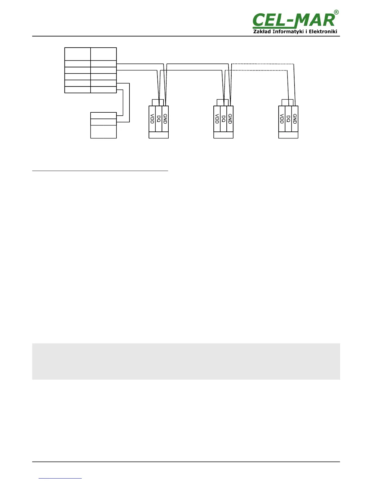
Fig 6. Sensor connection to ADA-401WP module with (2-wire) 1-WIRE network
3.4.2. SUPPORTED SENSORS WITH 1-WIRE INTERFACE
To ADA-401WP module can be connected devices like :
– based on circuits: DS1820, DS18S20, DS18B20, DS1822, DS2438Z, DS2401,
– temperature sensors DTS-103 & DTS107,
– environmental parameter sensor DES-200 (temperature, relative humidity, atmospheric pressure),
– environmental parameter sensor DES-216 (temperature, relative humidity, atmospheric pressure, lighting),
– environmental parameter sensor DES-300 (temperature, relative humidity, atmospheric pressure, lighting, sunlight, CO2
concentration),
– PT100 sensor to 1-WIRE converter DES-216-PT100,
– PT500 sensor to 1-WIRE converter DES-216-PT500,
– PT1000 sensor to 1-WIRE converter DES-216-PT1000,
– Analog signal 0-10V DC to 1-WIRE converter DES-216-U,
– Analog signal 0-20mA DC to 1-WIRE converter DES-216-I,
Method of connection above sensors to ADA-401WP is shown in user manuals of above devices.
3.4.3. SUPPORTED CIRCUITS WITH 1-WIRE INTERFACE
ADA-401WP module supports 1-WIRE interface circuits like: DS1820, DS18S20, DS18B20, DS1822, DS2438Z, DS2401.
In preparation DS2401 circuit.
3.4.4. 1-WIRE NETWORK LIMITATION
The maximum length of 1-WIRE network as layouts producer can be even 400m and the maximum number of sensors can be 500.
However, when building the network, remember that, each sensor is a shortening of 0,5 meters and 100 meters of cable causes
additional capacity load data line 5nF increasing signal distortion.
The real 1-WIRE network length and number of sensors will be less and will depend on:
– type of cables,
– topology connections,
– quality connections,
– interference from external electromagnetic fields.
RECOMMENDATIONS :
– using one type of the cable, we recommend computer twisted cables UTP 4x2x0,5, for 1-WIRE bus,
– 1-WIRE network connection in linear topology or use the passive 1-WIRE network splitter DNB-400,
– ending the 1-WIRE network by sensor,
– connecting unused wires and screen cable to PE rail of electrical installation.
– powering ADA-401WP module from individual power supply.
3.5. POWER SUPPLY CONNECTION
The power supply to ADA-401WP module should be DC (regulated) from 10 V to 30V and minimum nominal power should be 3W,
e.g. ZS-12/250 or DR-15-12. Power cable from DC power supplies to device must not be longer than 3m.
Observe the polarity, connect positive (+) of DC power supplies to V+ and negative (-) end to V- terminal. ADA-401WP has the
protection from opposite connection power supply. If after power, on the front panel is not lit green LED PWR, check the power
connection (polarity).
8