11
ENG
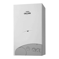
2.7.1 Separate flue kit (fig. 8)
The separate flue kit code 8089909 is sup-
plied with an intake diaphragm which must
be used as shown in fig. 8/a, depending on
the maximum load loss permitted in both
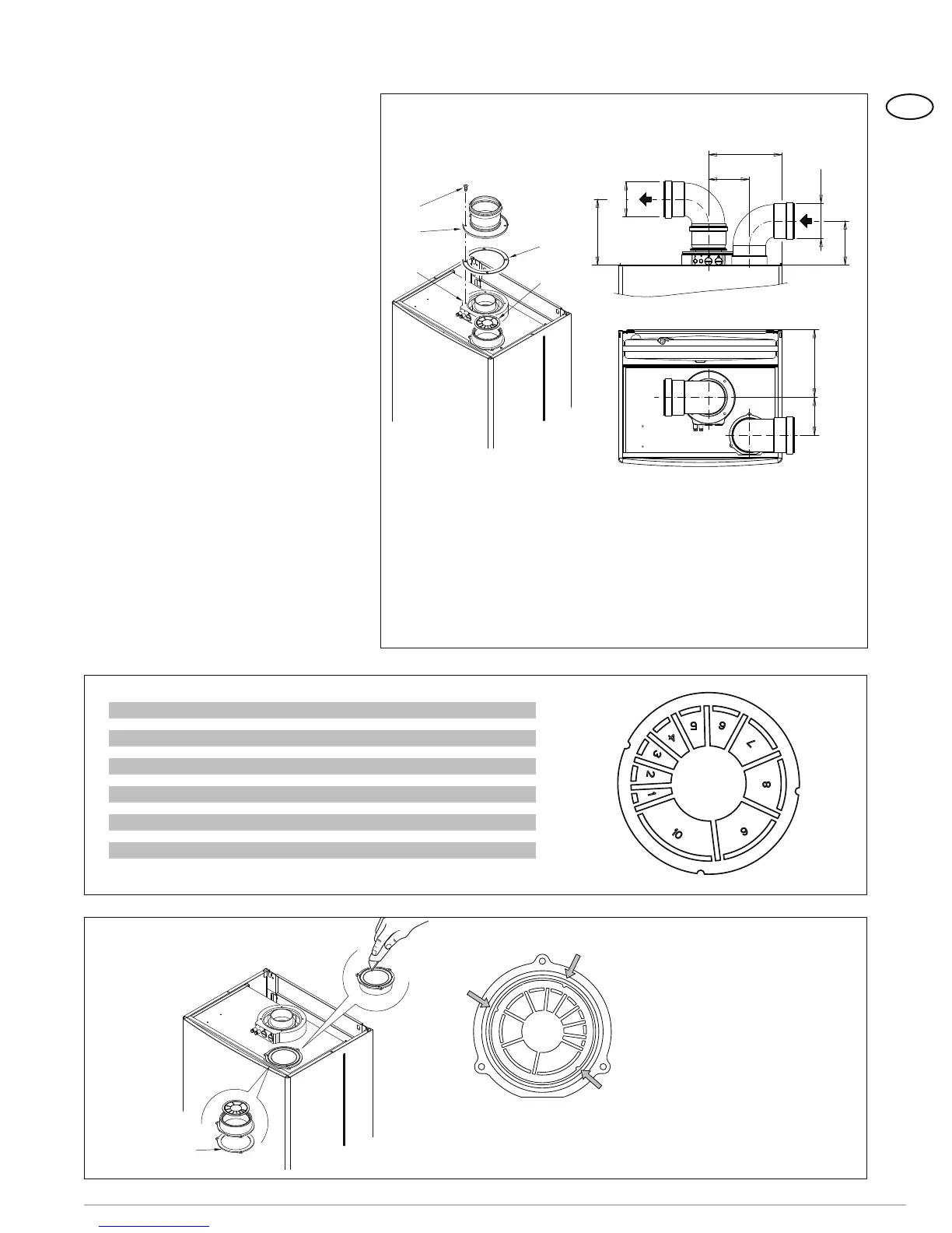
flues. To use the air intake in this type of
outlet you must perform the following ope-
rations (fig. 9):
1 Remove the base of the air intake, using
a tool to cut it off (a);
2 Overturn the air intake (b) and replace
the seal (5) with the seal supplied in the
kit code 8089909;
3 Insert the intake diaphragm supplied in
the kit code 8089909, pushing it in until
it is in contact with the bottom bead.
You can now insert the extension or curve
in its housing to complete the intake. You
need not use any seal or sealant, as gasket
provided is sufficient.
2.7.2 Outlet systems
The diagrams in fig. 9/a illustrate a num-
ber of examples of different types of sepa-
rate outlets.
2.8 POSITIONING OF OUTLET
TERMINALS (fig. 11)
The outlet terminal must be flush with the
wall and the inlet terminal must protrude
50 mm (2 in) from the outstide wall at
least.
a
b
5
Figure 9
Figure 8/a
N° segments to remove Load loss (mm H
2
O) (“W.C.H
2
O)
n° 1 and 2 0 - 1.0 0 - 0.039
from n° 1 to 3 1.0 - 2.0 0.039 - 0.079
from n° 1 to 4 2.0 - 3.0 0.079 - 0.12
from n° 1 to 5 3.0 - 4.0 0.12 - 0.16
from n° 1 to 6 4.0 - 5.0 0.16 - 0.20
from n° 1 to 7 5.0 - 6.0 0.20 - 0.24
from n° 1 to 8 6.0 - 7.0 0.24 - 0.28
from n° 1 to 9 7.0 - 8.0 0.28 - 0.31
from n° 1 to 10 8.0 - 10.0 0.31 - 0.39
without diaphram 10.0 - 12.0 0.39 - 0.47
IMPORTANT: The three housings
on the diaphragm permit assem-
bly of the air intake in one position
only.
165
110
165
K
ø 80
ø 80
100
92
1
2
3
4
6
Figure 8
KEY
1 (ø 125/95 mm - ø 4.92/3.74 inch) sponge seal
2 Fixing screw
3 Flue outlet flange
4 Inlet air diaphragm
6 Manifold with intakes
205 (8.07”)
100 (3,94”)
(4.33”)
(6,5”)
(ø 3“)
(ø 3“)
(6.5”)
(3.62”)