25
ENG
4.1 D.H.W. TEMPERATURE
ADJUSTMENT
The system with a potentiometer for adjusting
the temperature of D.H.W. with a setting
range from 30° to 60°C (86-140 °F) offers a
double advantage:
1) The boiler adapts perfectly to any type of
D.H.W. system, whether the mixing system
is a mechanical or a thermostat-controlled
type.
2) The thermal output is dosed according to
the temperature required, which means a
considerable saving in fuel.
NOTE: In order to avoid any misunderstanding
please remember that the value obtained by
the product of temperature difference (in °C)
between D.H.W. output and input into the
boiler by the hourly flow rate measured on the
tap, where hot water is drawn off (l/h), cannot
be higher than the useful output developed by
the boiler.
For measurements and checks on flow rate
and temperature of D.H.W., use suitable
instruments, taking into consideration any
heat dispersion along the stretch of piping
between the boiler and the measuring point.
4.2 ADJUSTMENT OF
D.H.W. FLOW RATE
To adjust the D.H.W. flow rate, use the flow rate
adjuster (5 fig. 5).
Remember that the flow rates and correspon-
ding temperatures of use of hot water have
been obtained by positioning the selector of the
circulation pump on the maximum value.
Should there be any reduction in the D.H.W.
flow rate, the filter installed on the inlet to
the divertor valve (3 fig. 5) will need cleaning.
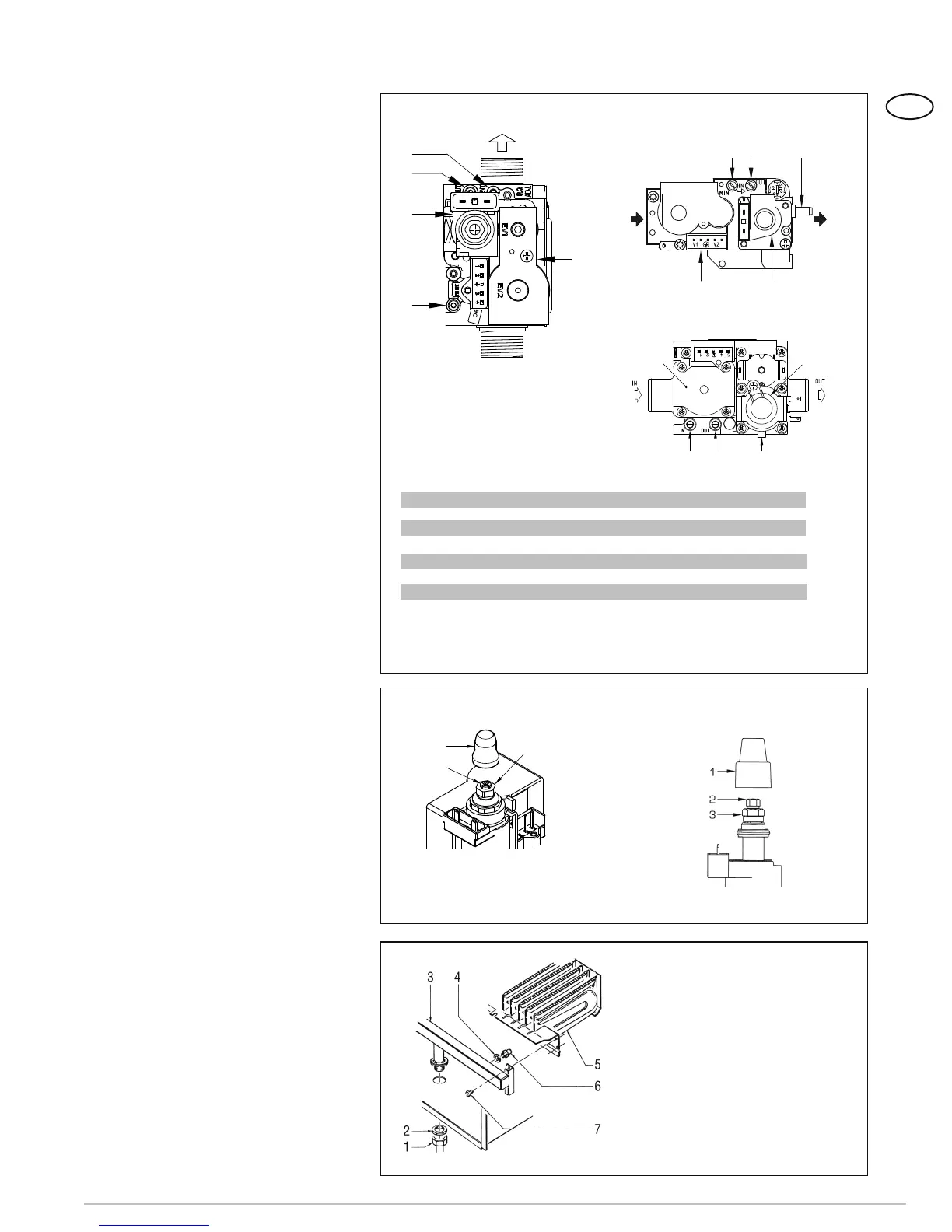
4.3 GAS VALVE
The boilers are equipped standard with the
SIT 845 SIGMA/HONEYWELL VK 4105M /
SIEMENS VGU 50 gas valve (fig. 21).
The gas valve is set at two pressure values:
maximum and minimum. According to the
type of gas burnt, these correspond to the
values given in Table 4.
The gas pressures at the maximum and mini-
mum values, are factory set. Consequently
they must not be altered. Only when you
switch the appliance from one type of gas
supply (methane) to another (propane), it is
permitted to alter the operating pressure.
4.4 GAS CONVERSION
This operation must be performed by autho-
rised personnel using original Sime compo-
nents.
To convert from natural gas to LPG or
vice versa, perform the following operations
(fig. 22):
3
2
1
KEY
1 Plastic tap
2 Minimum pressure adjusting nut
3 Maximum pressure adjusting nut
SIT 845 SIGMA HONEYWELL VK 4105M
SIEMENS VGU 50
KEY
1 Swivel connection 1/2”
2 Locknut 1/2”
3 Burner manifold
4 Washer ø 6.1
5 Burners
6 Nozzle M6
7 Screw
WARNING: To ensure a perfect seal,
always use the washer (4) supplied in
the kit when replacing nozzles, even in
burner units for which it is not specified.
Figure 22
Figure 22/a
3
4
2
1
5
6
1
2
4
3
5
SIT 845 SIGMA HONEYWELL VK 4105M
KEY
1 Modulator
2 EV1-EV2 coils
3 Pressure inlet upstream
4 Pressure inlet downstream
5 VENT pressure test point
1
2
3 4 5
TABLE 4
Burner maximum pressure Modulator current
Fuel mbar W.C. mA
Natural Gas* 13.7 5.5 130
Propane 24.9 10 165
Burner minimum pressure Modulator current
Fuel mbar W.C. mA
Natural Gas* 5.0 2.0 0
Propane 8.7 3.5 0
(*) Max. burner pressure is guaranteed only when the supply pressure exceeds the max.
burner pressure by at least 3 mbar (1.2” W.C.).
Figure 21
SIEMENS VGU 50
4 USE AND MAINTENANCE