22
ENG
3.1 ELECTRONIC BOARD
The electronic boards are manufactured in
compliance with the ANSI and Canadian direc-
tives.
They are supplied with 120V and, throu-
gh a built-in transformer, send a voltage of
24V to the following components: modula-
tor, D.H.W./C.H. sensors, room stat, water
flowmeter/water pressure switch, pressure
switch valve, flue gas thermostat/flue gas
pressure switch, safey thermostat and time
programmer.
An automatic and continuous modulation
system enables the boiler to adjust the heat
output to the various system requirements or
the User’s needs.
The electronic components are guaranteed
against a temperature range of 0° to
+60°C (32°-140° F)
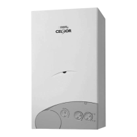
3.1.1 Fault finding
The indicator leds signalling irregular and/
or incorrect operation of the equipment are
indicated in fig. 14.
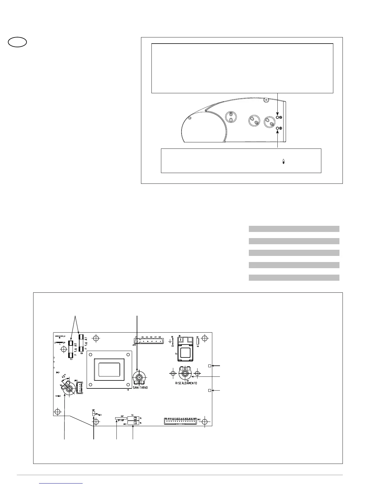
3.1.2 Devices
The electronic board is equipped with the
following devices (fig. 15):
– Connector “METANO-GPL” (4)
With the connector disconnected, the boiler
is ready to function with METHANE; with the
connector connected with GPL.
ATTENTION: It is essential that the ope-
rations described above be carried out by
authorized technical staff.
3.2 TEMPERATURE
SENSOR
Antifreeze system made up of the NTC hea-
ting sensor that activates when the water
temperature reaches 6°C (43 F).
The sensor acts as a limit stat, switching-off
the burner when the temperature measured
is higher than 85°C (185 F); the reset tempe-
rature is set at 80°C (176 F).
When sensor has tripped, the boiler will not
function for either service.
Table 3 shows the resistance values ( ) that
are obtained on the sensor as the tempera-
ture varies.
1
2
1045
3
7
8
9
Figure 15
KEY
1 Jumper JP2
2 Fuse (1,6 AT)
3 D.H.W. potentiometer
4 Connector “METHANE/GPL”
5 Rotay switch
7 Block red led
8 C.H. potentiometer
9 Bi-colour led gree/orange
10 Connector “TA”
Figure 14
Red led on, ignition blocked/safety stat tripped:
turn the rotary switch in the position ( )
to restore functioning
3 CHARACTERISTICS
Bi-colour green led off if power is cut-off.
Bi-colour orange led: C.H. sensor (SM) fault.
Green led flashing: fan/smoke pressure switch/smoke stat failure.
Orange flashes on water circulation.
Flashing red led indicates a problem in the tap water probe (SS)
TABLE 3
Temperature Resistance
°C °F (Ω)
20 68 12.090
30 86 8.313
40 104 5.828
50 122 4.161
60 140 3.021
70 158 2.229
80 176 1.669