21
ENG
CN6
CN2
CN7
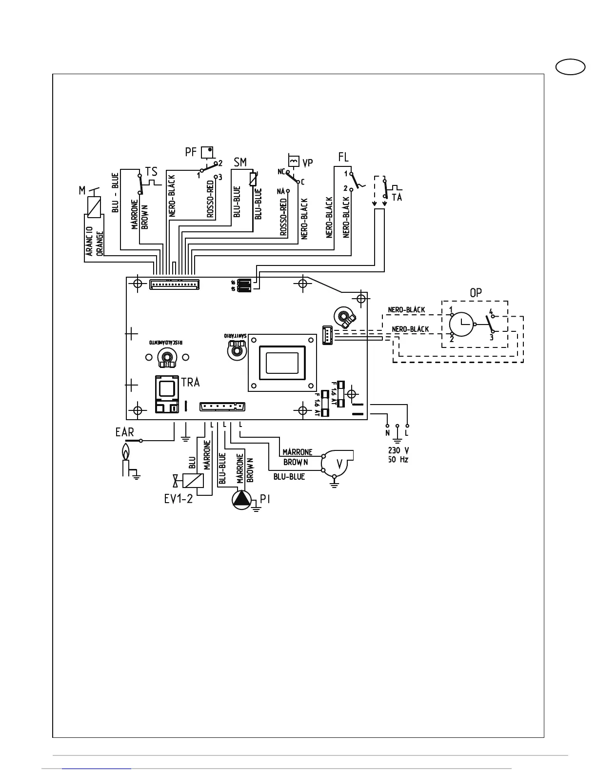
KEY
F Fuse (1.6 AT)
PI C.H. pump
EV1-2 Gas valve coil
V Fan
PF Smoke pressure switch
VP Divertor valve
M Modulator
SM C.H. sensor
SS D.H.W. probe
TA Room stat
EAR
Ignition/detection electrode
TRA Ignition transformer
TS 100°C (212°F) safety stat
PA Water pressure switch
FL Flowmeter
TF Smokes stat
OP Time programmer
Nota: The room stat or the programmable
thermostat must be connected to terminals
15-16 of the “TA” connector after having
removed the bridge.
Figure. 13
2.9.3 Wiring diagram
CONNECTOR SPARE PART CODES:
CN2 code 6299909
CN6 code 6299906
CN7 code 6299907
120V
60Hz