26
ENG
1. Close the gas cock.
2. Disassemble the burner manifold (3).
3. Replace the main nozzles (6) supplied in a
kit, inserting the copper washer (4). Use a
ø 7 wrench to perform this operation.
4.
Remove the “METANO/GPL” connector
link on the card and set it in the position
corresponding to the gas to be used
(4 fig.
15).
5. To set the values of maximum and mini-
mum gas pressure, follow the instructions
given in section 4.5.1.
6. After have ultimated the conversion of the
boiler, please stick onto the casing panel
the plate showing the relevant flue which is
included conversion kit.
NOTE: When reassembling components
which you have removed, replace gas seals;
test all gas connections after assembly
using soapy water or a product made spe-
cifically for the purpose, being sure not to
use open flame.
4.4.1
Adjusting valve pressure
Set maximum and minimum pressure on gas
valves as follows (fig. 22/a):
1. Connect the column or a manometer to
the intake downstream of the gas valve.
Disconnect the valve VENT pressure test
point tube (5 fig. 21).
2. Remove the cap (1) from the modulator.
3. Place the hot tap water potentiometer
knob at the maximum position.
4. Turn on the boiler using the four-way
switch and turn on a hot water tap all the
way.
5. Remember that rotating clockwise will
increase pressure while rotating anti-
clockwise will diminish it.
6. Adjust maximum pressure using the nut
(3 fig. 22/a) with a wrench to the maxi-
mum pressure value indicated in Table 4.
7. Do not adjust minimum pressure until you
have adjusted maximum pressure.
8. Turn off the supply power to the modula-
tor, and keep the hot water tap turned on.
9. Lock the nut (3) in place, turn the screw
/nut (2) to the minimum pressure indica-
ted in Table 4.
10. Turn off the boiler and turn it back on
again several times, keeping the hot water
tap turned on at all times and checking
that the maximum and minimum pressu-
re values correspond to the established
values; correct the settings if necessary.
11. Adjust, checking that you have restored
the power to the modulator.
12. Put the pipe back on the valve VENT pres-
sure test point.
13. Remove the manometer, remembering to
tighten the screw for closing the pressure
test point.
14. Put the plastic cap (1) back on the modu-
lator and seal with a drop of coloured
sealant if necessary.
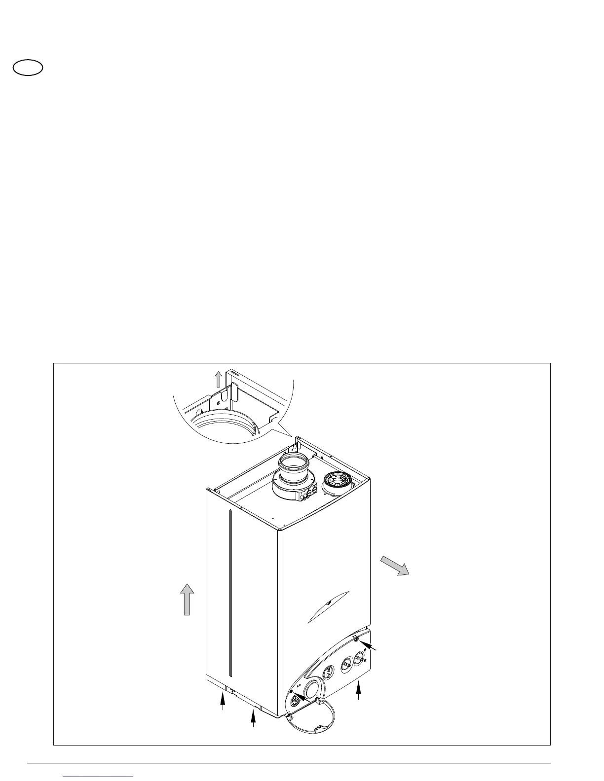
4.5 REMOVAL OF OUTER CASING
The casing may be removed completely to faci-
litate boiler maintenance, as shown in fig. 23.
4.6 CLEANING AND
MAINTENANCE
Carry out the cleaning of the generator in
the following way:
1. Unplug the power cord to the boiler and
close the gas feed cock.
2. Remove the outer casing and the gas bur-
ner manifold unit . To clean the burner,
blow in a jet of air, so as to remove any
dust particles that may have accumula-
ted.
3. Clean the heat exchanger, removing any
dust or residue from combustion. When
1
2
Figure 23
Before remove the five screws .......
......then to raise
.......at last to pull