SKU 40643 For technical questions, please call 1-800-444-3353. Page 4
20. Avoid flammable liquids. To avoid possible fires, never use sander near flammable
liquids, vapors, or gases.
21. Avoid breathing dust. Wear a dust mask over your mouth and nose.
Note: Performance of this tool may vary depending on variations in local
line voltage. Extension cord usage may also affect tool performance.
Warning: The warnings, cautions, and instructions discussed in this in-
struction manual cannot cover all possible conditions and situations that
may occur. It must be understood by the operator that common sense and
caution are factors which cannot be built into this product, but must be
supplied by the operator.
Unpacking
When unpacking, check to make sure the tool is assembled and all parts present. Refer to
the Assembly Drawing at the end of this manual. If any parts are missing or broken, please
call Harbor Freight Tools at the number on the cover of this manual as soon as possible.
Using Extension Cords
When using extension cords, they must have a minimum wire size depending on the amper-
age of the tool and the length of the extension cord. This size is signified by its AWG rating;
the smaller the gauge, the greater the cable’s capacity. The extension cord must have a
grounding prong. For this Belt Sander, use an extension cord rated at 16 AWG for lengths up
to 50 feet.
Assembly
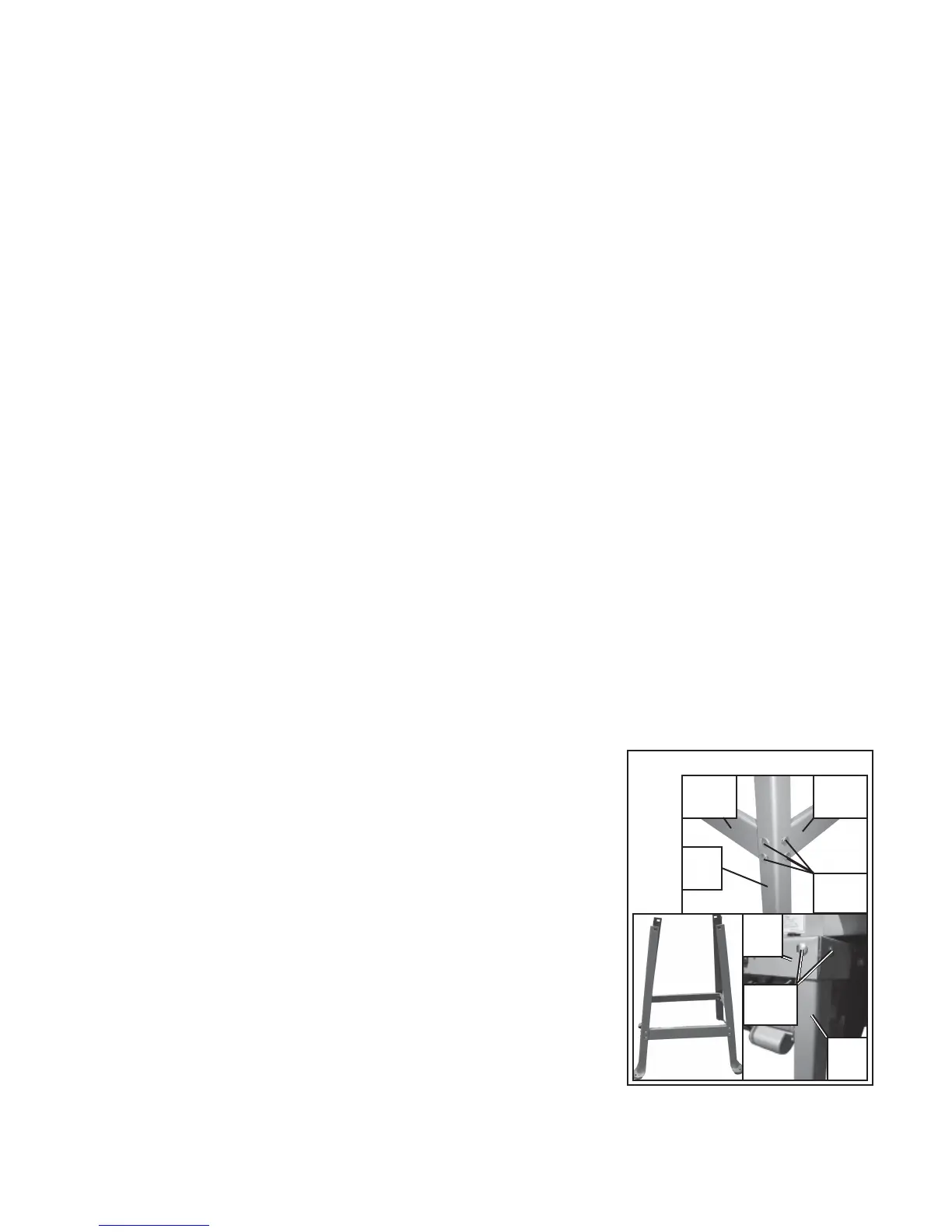
Stand Assembly
1. Join each Leg (74) to both a short Frame (75) and a long
Frame (76) using 4 Screws (73), Nuts (12), and Washers
(13), as shown in Stand Assembly A. The two short
Frames should be on opposite sides from each other
giving the stand a rectangular shape, if viewed from the
top.
2. The Nuts should be snug and hold the stand together but
not be fully tightened yet- see Stand Assembly B.
Warning! This entire unit weighs 139 Lbs.
At least 2 able assistants should be
used to put this tool on its stand safely.
3. Have at least two assistants hold the Base (46) over the
stand. Line up one of the narrower ends of the stand with
one of the smaller ends of the Base (46) (for example, the end that the on/off switch is
located on.) Place the top of the Leg (74) under the corner of the Base, lining up the
Stand Assembly
A
B
C
Screw
(73)
Leg
(74)
Frame
(75)
Frame
(76)
REV 01/04
Base
(46)
Screw
(73)
Leg
(74)