SKU 40643 For technical questions, please call 1-800-444-3353. Page 5
Operation
Sanding Safety Tips
1. Always maintain a maximum of 1/16 inch clearance between the table and the
Sanding Belt or Disc.
2. Do not use the right side of the disc for sanding. The material could kick back.
3. Hold material securely while sanding to avoid kick back.
Leveling Table Assembly
During this and other procedures, refer to the photo on the next page and the Assembly
Drawing on the last page.
1. Place a combination square on the Table (41) so that it also touches the sanding Paper
(23).
If the Table is 90 degrees to the Pad, the square is flush on the Pad.
2. If the Table is not 90 degrees with the Pad, loosen the table angle Lock Handle (32)
and tilt the Table until the square is flush with the Pad.
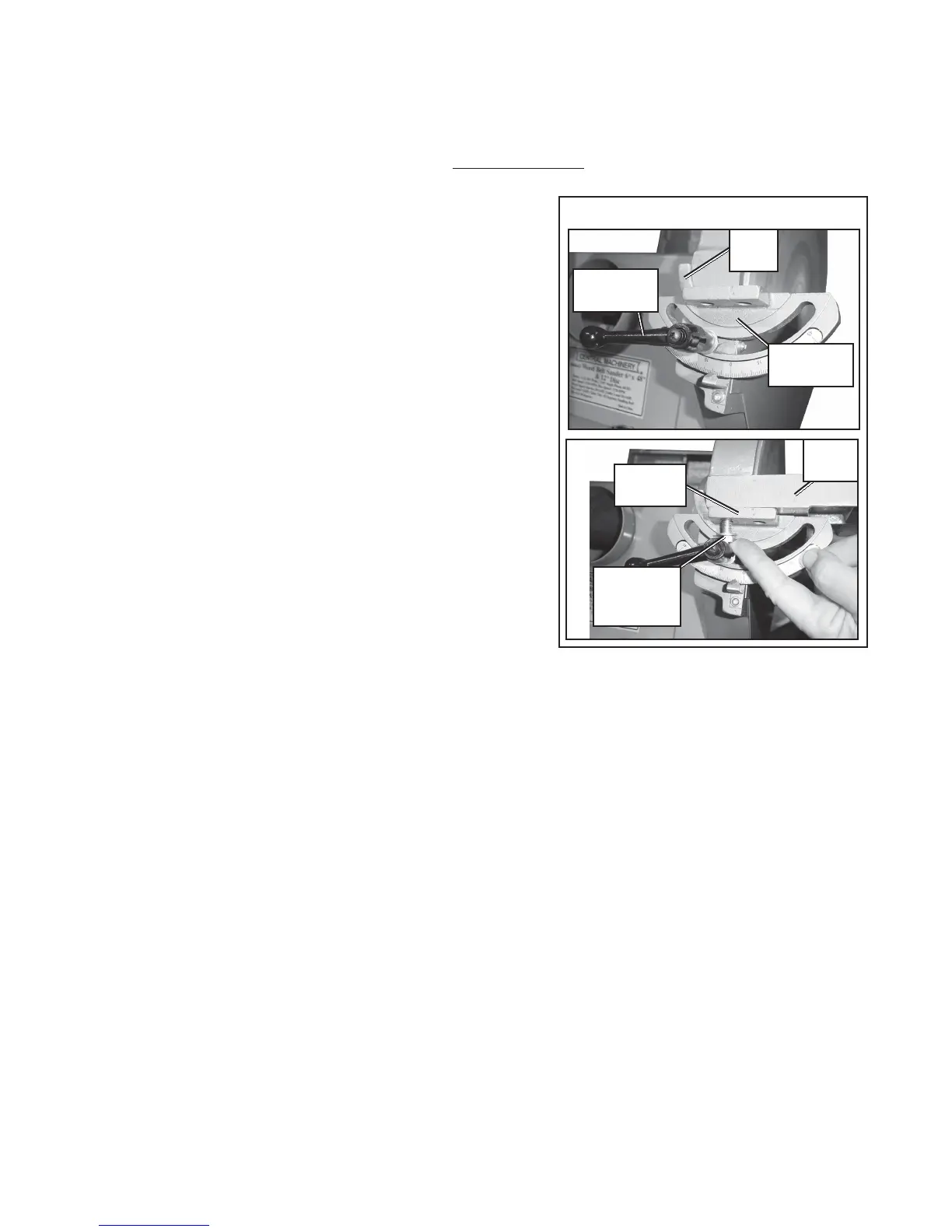
Disc Sander Table Assembly
1. Remove both Trunnions (33) from the sides of the
Table (41), set the Screws (38) and Washers (13)
aside.
2. Place a Trunnion (33) on the side of the Disc
Cover (42) so that the groove on the underside
of the Trunnion fits over the Slide (35). Secure
with a Lock Handle (32) and Washer (13). Leave
the Lock Handle loose for now so the Trunnion
can still pivot. (See Table Assembly A.) Repeat
for the other side.
3. Place the Table (41) on top of both Trunnions (33)
lining up the bolt holes. Reattach the Table to
the Trunnions using the Screws (38) and Washers
(13) set aside in step 1. (See Table Assembly
B.) Level the table, as described in Leveling
Table Assembly below, and tighten all hardware.
holes. Attach using 2 Screws (73), Nuts (12), and Washers (13). Repeat for all corners,
leaving all hardware snug, not tight. Once all hardware is in place, tighten all Nuts securely,
including the Nuts from step 1. After all hardware is secure, the assistants can release
the base.- see Stand Assembly C,
previous page.
REV 01/04
A
Lock
Handle (32)
B
Trunnion
(33)
Table
(41)
Table Assembly
Screw (38)
and
Washer (13)
Trunnion
(33)
Slide
(35)