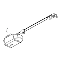
OPERATOR INSTALLATION
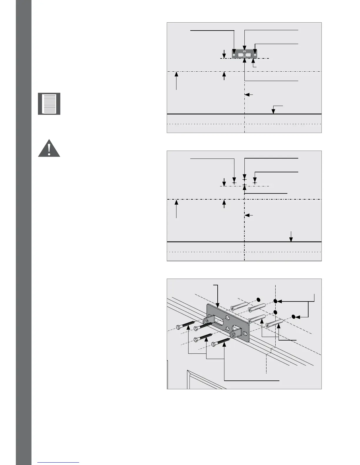
FIGURE 15
FIGURE 16
FIGURE 17
Garage door center line
Garage door center line
Header bracket
(Note the orientation)
Hole B
Hole C
Hole D
(Optional)
Hole B
Hole C
Hole D
(Optional)
Coach screws
Hole A
Hole A
Header bracket
Plugs
11mm
Holes
Garage door
Garage door
Highest arcing
point
Highest arcing
point
0-50mm
0-50mm
Place the header bracket on the
wall as shown in Figure 15.
Ensure that the bottom edge of
the bracket is level, and no more
than 50mm above the highest
arcing point of the garage door.
Mark the location of the four screw
holes (Hole A, B, C and D[optional]).
Drill four 11mm diameter holes in
positionof‘HoleA’,‘HoleB’,‘Hole
C’and‘HoleD’(optional),atleast
50mm deep.
Mounting the drive rail
more than 50mm above
the highest arcing point
of the garage door may
cause the drive rail to
ex excessively.
Note the orientation of the
header bracket.
Placeascherplugineachhole,
followed by the header bracket.
Secure it in position with at least
three coach screws (supplied)
(13mm hexagonal head).