EFFECTIVITY
ALL CFM56 ENGINES
CFMI PROPRIETARY INFORMATION
CFM56-ALL TRAINING MANUAL
BASIC ENGINE
PARTICULARS
BORESCOPE INSPECTION
Page 24
Sep 03
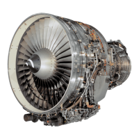
CFM56 MAIN CHARACTERISTICS
CFM56 engines consist of two independent rotating
systems:
- The low pressure system, with a rotational speed
designated N1.
- The high pressure system, with a rotational speed
designated N2.
Type of engine Turbo fan
Arrangement Two spool axial ow
Rotation Clockwise (ALF)
Fan & Booster Module
Fan Stage 1
(-2, -3, -5A, -7B) :
Booster Stages 2 to 4
(-5B, -5C) :
Booster Stages 2 to 5
(ALL) :
High Pressure Compressor (HPC) Module
Stages 1 to 9
Combustor Section
(-2, -3, -5A, -5C) :
Annular SAC
(-5B, -7B) :
Annular SAC (option DAC)
(ALL) :
High Pressure Turbine (HPT) Module
Stage 1
Low Pressure Turbine (LPT) Module
(-2, -3, -5A, -5B, -7B) :
Stages 1 to 4
(-5C) :
Stages 1 to 5
(ALL) :
Accessory Drive Module
Inlet Gearbox (IGB)
Transfer Gearbox (TGB)
Accessory Gearbox (AGB)