9. Ignition System
Pickup Coil
Note:
¾ Measure after all the wires are correctly connected.
¾ Inspect with compression pressure in the cylinder,
spark plug and spark plug cap are properly
installed. If the spark plug is removed and then do
the measurement, the peak voltage will rise.
Remove left side panel (→2-3)
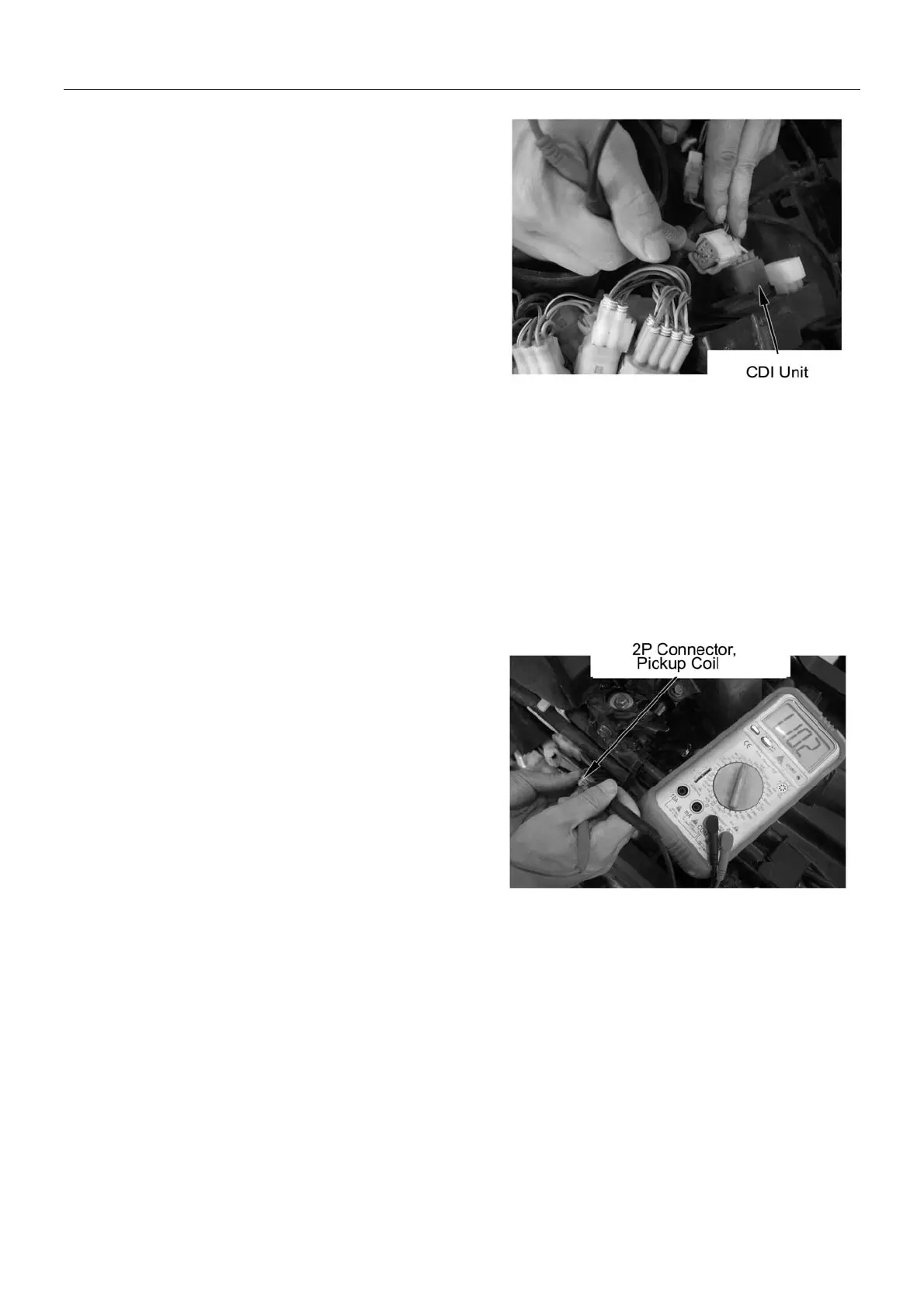
Disconnect CDI unit connector.
Connect peak voltage oscillograph terminal with the
following terminal of main cable.
Special tools
Peak voltage oscillograph 07HGJ-0020100
(Use together with digital multimeter available from the
market with input impedance over 10M/DCV)
Connecting terminal: blue/yellow (+) –green (-)
Turn ignition switch to the ON position, and start
engine.
Peak voltage: over 0.8V
Note:
When measuring the voltage, do not touch the
terminal with finger to avoid electric shock.
If peak voltage obtained from CDI unit connector is
improper, measure again the peak voltage on the AC
magneto 2P connector.
9-5