15. Engine Removal, Inspection & Installation
Bevel Gear
Note: Proper bevel gear engagement depends
on that the gear backlash and tooth contact are
within the proper range.
Bevel Gear Backlash
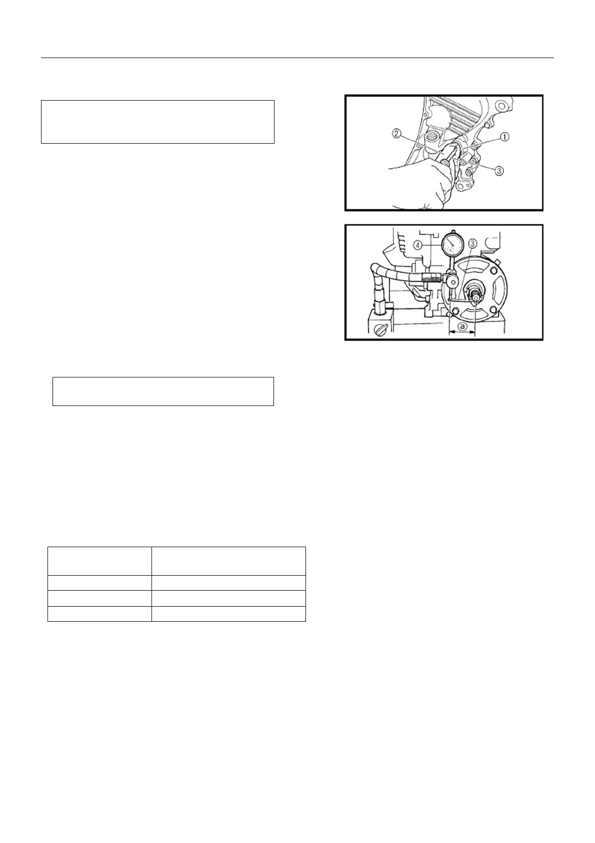
z Install drive and driven gears to the
crankcase. Wrap a (--) screwdriver ③with a
rag ② and insert it into the speed sensor
hole ① of left crankcase to fix the drive
bevel gear.
z Install special tool ③ and micrometer ④.
Tool: Bevel gear side clearance dial gauge
Micrometer
a=46mm
z Turn the driven bevel gear in each direction
and measure the backlash.
z If the backlash is not within the
specification, adjust the thickness of the
driven bevel gear adjust washer. Re-check
the backlash until the backlash is correct.
Bevel Gear Backlash: 0.1-0.2mm
Adjustment
NOTE: Measure four points in the mutual
vertical direction
Measured Backlash Washer Thickness
Adjustment
<0.1mm Decrease washer thickness
0.1~0.2m
Correct
>0.2mm Increase washer thickness
15-44
 Loading...