CG Drives & Automation, 01-5326-01r5 Control Connections 49
4.3 Inputs configuration
with the switches
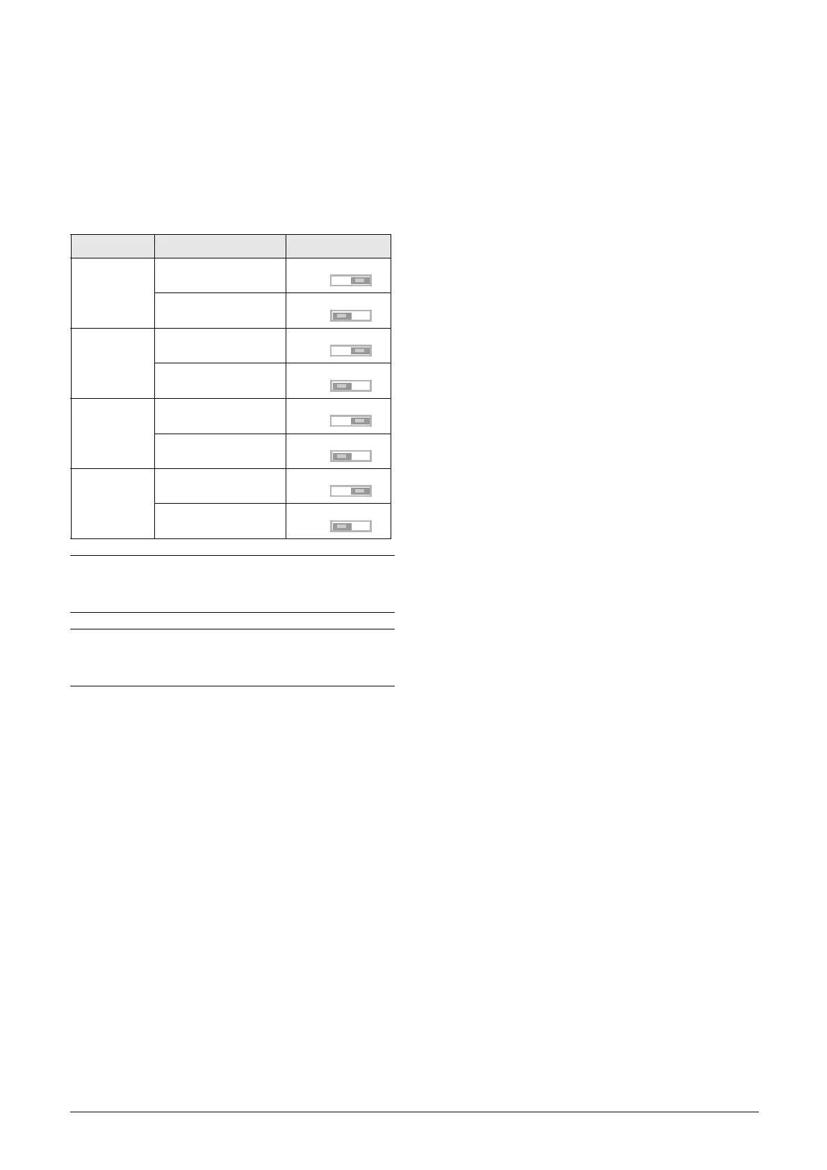
The switches S1 to S4 are used to set the input configuration
for the 4 analogue inputs AnIn1, AnIn2, AnIn3 and AnIn4
as described in table 22. See Fig. 56 for the location of the
switches.
Table 22 Switch settings
Input Signal type Switch
AnIn1
Voltage
S1
Current (default)
S1
AnIn2
Voltage
S2
Current (default)
S2
AnIn3
Voltage
S3
Current (default)
S3
AnIn4
Voltage
S4
Current (default)
S4
NOTE: Scaling and offset of AnIn1 - AnIn4 can be
configured using the software. See menus [512],
[515], [518] and [51B] in section 11.7, page 166.
NOTE: the 2 analogue outputs AnOut 1 and AnOut 2
can be configured using the software. See menu [530]
section 11.7.3, page 174
U
I
U
I
U
I
U
I
U
I
U
I
U
I
 Loading...
