35
14.9 Completion
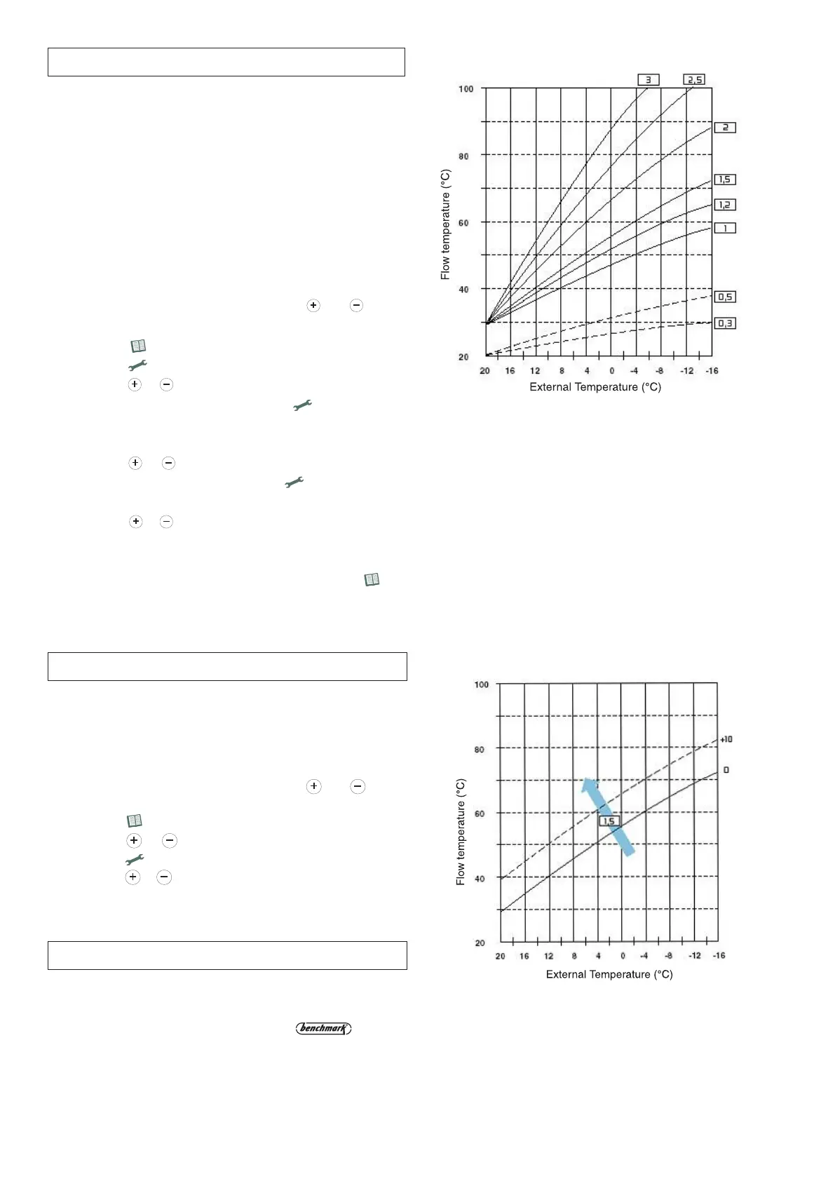
14.8 Adjusting the parallel shift
TABLE D
TABLE E
In the event that the thermal curve set is giving too high or
too low a temperature, there are two options, you can either
alter the thermal curve as described in Section 14.7 or adjust
the parallel shift of the curve.
To adjust the parallel shift, proceed as follows:
1. Access the settings menu by pressing the and
buttons together for five seconds;
2. Press the button 5 times to access Menu 6;
3.
Press the or buttons to access Menu 6.3;
4. Press the button, the 3rd and 4th digits will flash;
5. Press the or buttons to adjust the parallel shift up
and down in steps of 1 between 0 and 20 (see
Table E).
For the Republic of Ireland it is necessary to complete a
“Declaration of Conformity” to indicate compliance to I.S.813.
An example of this is given in the current edition of I.S.813.
In addition it is necessary to complete the
Commissioning Checklist in Section 24 of this manual (Page
60).
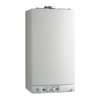
14.7 External sensor set-up (where fitted)
When using an outdoor sensor, the microprocessor-
c
ontrolled PCB will select the most suitable flow
temperature, taking into account the external temperature
and the type of system. The microprocessor is capable of
doing this because it is possible to establish a link between
t
he external temperature and the flow temperature of the
Central Heating system water. This link translates into a
“
thermal curve”.
The type of curve should be chosen in correspondence with
t
he planned temperature of the system and the nature of the
heat loss present in the building.
To set up the external sensor, proceed as follows;
1. Access the settings menu by pressing the and
buttons together for five seconds;
2. Press the button 5 times to access Menu 6;
3
. Press the button, the 3rd and 4th digits will flash;
4. Press the or buttons to change from 1 (sensor not
fitted ) to 0 (sensor fitted) and press the button again
to select the change;
5. Select the thermal curve required from
Table D;
6. Press the or buttons to change to Menu 6.2;
7. To adjust the thermal curve, press the button, the 3rd
and 4th digits will begin to flash;
8. Press the or buttons to select the parameter that
best meets your temperature requirement shown in
Table
D
(opposite);
9. Once the correct parameter has been set, press the
button again to confirm the selection.
CO
NVECTOR
RA
DIATOR
-CU
RVES
2.5 T
O
3
ST
EEL
RA
DIATOR
-CU
RVES
1.5 T
O
2
O
V
ERSIZED
ST
EEL
RA
DIATOR
-CU
RVES
1 T
O
1.2
U
NDERFLOOR HEATING -CURVES 0.3 TO 0.5*
*WHERE CURVE 0.3 OR 0.5 (UNDERFLOOR HEATING) ARE
SELECTED
, A SUITABLE SYSTEM SAFETY THERMOSTAT MUST BE
CONNECTED TO THE MAIN PCB TERMINAL 14 (SEE Fig. 32, page
26) IN ORDER TO PROTECT THE UNDERFLOOR HEATING SYSTEM.
 Loading...