5
USER’S INSTRUCTIONS
1. Control Panel
30
26
25
34
28
Fig 1
33
31
32
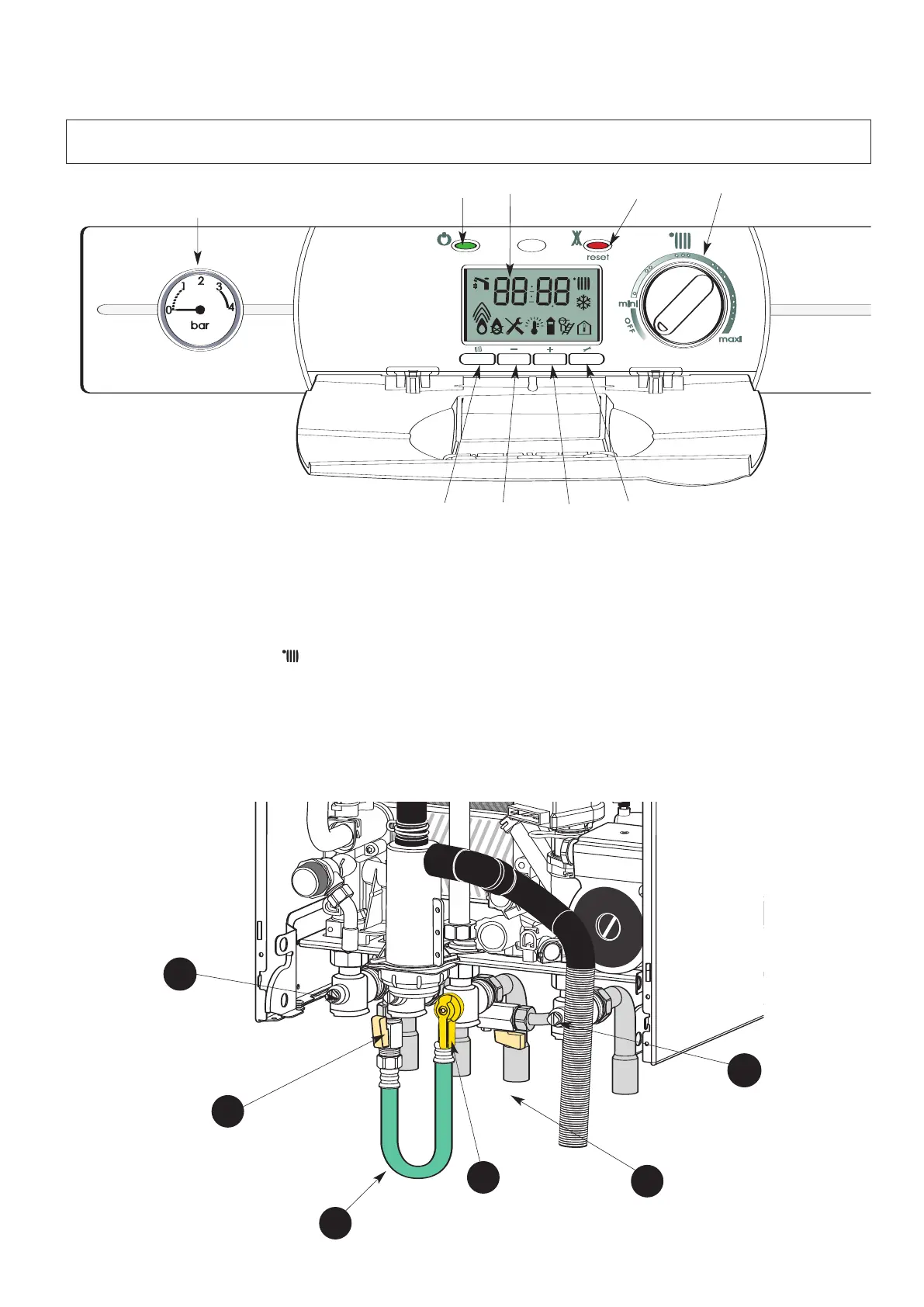
Control panel (Fig.1)
16.- Pressure Guage
25.- Display
26.- On/off push button and power on indicator light
28.- Reset push button and red indicator lockout light
30.- Central Heating control knob and temperature setting
31.- Menu key
32.- Reducing key
33.- Increasing key
34.- Setting key
Connecting bracket
Taps shown in Open position (Fig. 2)
39 : Gas service tap
41 : Central heating flow isolating valve
42 : Central heating return isolating valve
43 & 44: Filling taps
45 : Filling loop
Fig. 2
41
42
43
44
45
39
16
 Loading...