55
18.4.2 Removing the fuses
1. Carry out step 18.4.1;
2. Remove the fuses “X” (see Fig. 105)
3. Reassemble in reverse order.
NOTE: FUSE
RATING
= 2 AMP
FAST FUSE
Fig. 105
Fig. 104
W5
X
Fig. 103
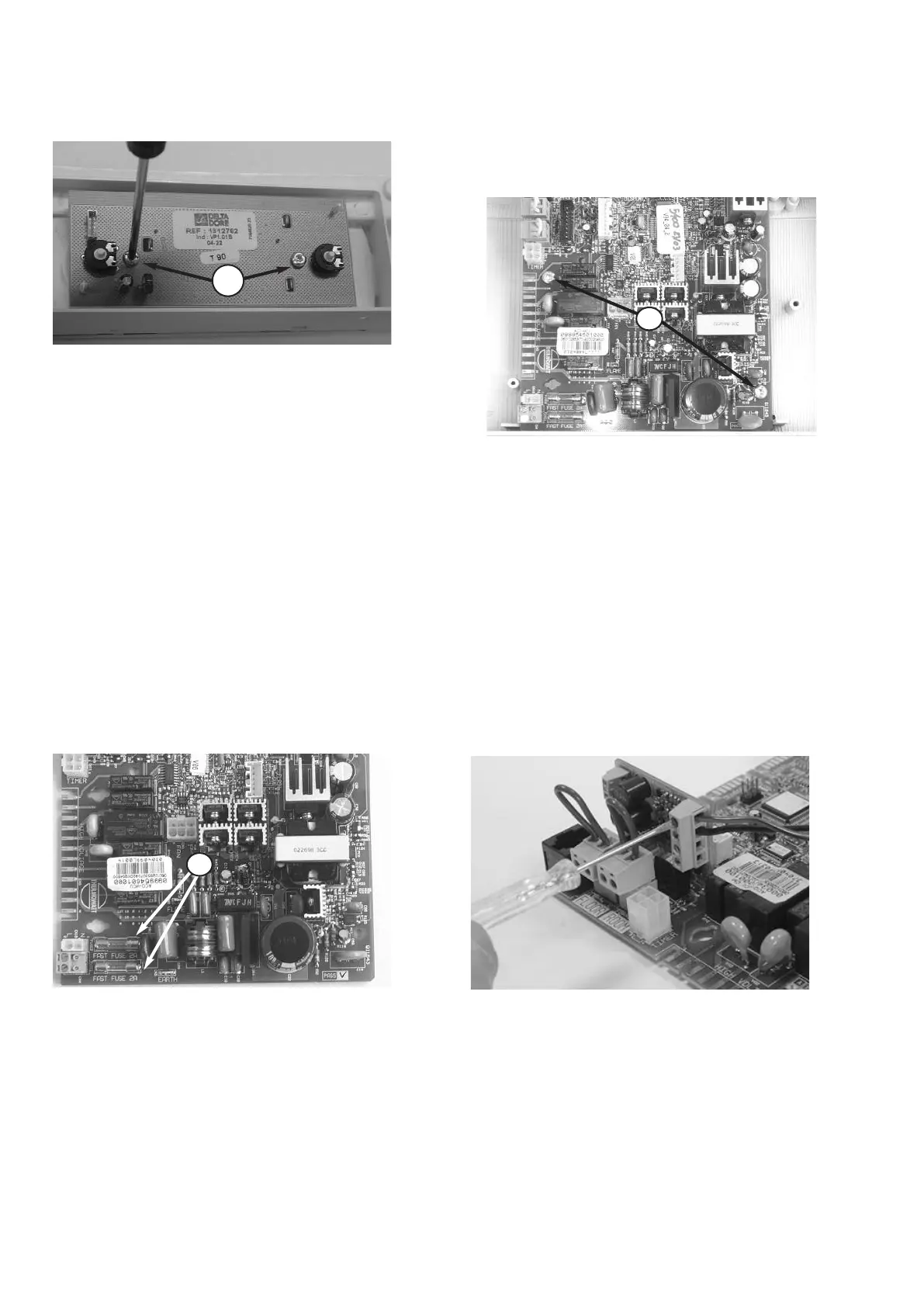
8. To remove the main PCB disconnect all electrical
c
onnections and remove the two screws
W
5
(
see
Fig. 104);
F
it the correct EEPROM key when replacing the
old PCB.
9. Reassemble in reverse order.
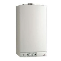
6. To remove the display PCB, remove the two
s
crew
W
4
a
nd lift the PCB out (see
F
ig. 103
)
;
7. Reassemble in reverse order;
18.5 Connecting the external sensor
Fig. 106
1. Access the main PCB as in step 18.4.1;
2. Install the interface PCB supplied in the
external sensor kit on the main PCB (see Fig.
106)
3. Connect the wires between the external
sensor and the interface (see Fig. 106).
W4
 Loading...