15
INSTALLATION
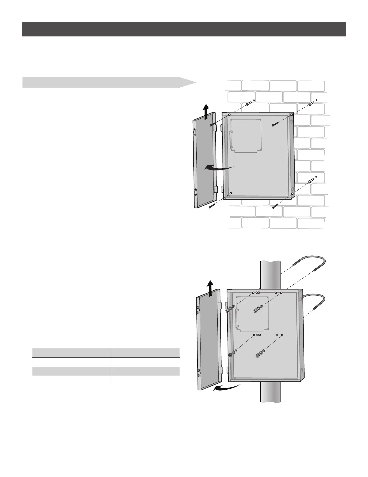
POST MOUNT
NOTE: The post mount option is not recommended for the 33AH battery
application.
1. Open the control box. The control box door may be removed by
opening the door 90°. Lift the door from the hinges and set aside
until the installation is complete.
2. The control box can be mounted to a post with 'U' bolts (refer to
chart). The knock out will accommodate a 3/8" diameter 'U' bolt.
Select center mounting holes (top and bottom) and knock out using a
screwdriver and hammer.
3. Secure the control box to mounting surface with U-bolts and rubber
washers (not provided) to ensure a watertight seal.
TYPE AND SIZE 'U' BOLT OPENING
Standard 3" Round Pipe 3-1/2"
Standard 4" Square Post 4"
Standard 6" Square Post 6"
STEP 5 continued...
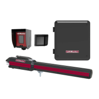
INSTALL THE CONTROL BOX
LARGE METAL CONTROL BOX (XLSOLARCONTU)
The control box MUST be mounted within 5 feet (1.52 m) of the gate
operator. Mount the control box as high as possible for best radio
reception. Make sure the control box is level.
WALL OR COLUMN MOUNT
1. Open the control box. The control box door may be removed by
opening the door 90°. Lift the door from the hinges and set aside
until the installation is complete.
2. Use knock outs located at the 4 corners of the control box and
knock out using a screwdriver and hammer.
3. Secure the control box to mounting surface using the provided
screws (4).
WALL OR COLUMN MOUNT
POST MOUNT