OPERATOR
REQUIRES EXTERNAL
MONITORED ENTRAPMENT
PROTECTION DEVICE
• THIS PRODUCT IS TO BE INSTALLED AND SERVICED BY A TRAINED GATE SYSTEMS
TECHNICIAN ONLY.
• This model is for use on vehicular passage gates ONLY and not intended for use on
pedestrian passage gates.
• This model is intended for use in Class I vehicular swing gate applications.
• Visit LiftMaster.com to locate a professional installing dealer in your area.
• This gate operator is compatible with MyQ
®
and Security+ 2.0
®
accessories.
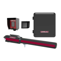
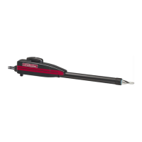
RESIDENTIAL DC SOLAR
VEHICULAR SWING GATE OPERATOR
Model LA412
INSTALLATION MANUAL
LA412PKGU
Single Arm Package
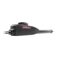
LA412DC
Primary 12 VDC Actuator Arm for single swing gate applications
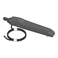
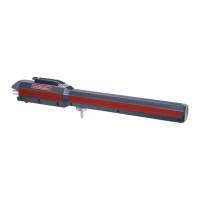
LA412DCS
Secondary 12 VDC Actuator Arm for dual swing gate applications
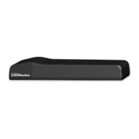
LiftMaster
845 Larch Avenue
Elmhurst, IL 60126-1196