To prevent possible SERIOUS INJURY or DEATH from electrocution:
• Be sure power is not connected BEFORE installing door control.
• Connect ONLY to 24 VOLT low voltage wires.
To prevent possible SERIOUS INJURY or DEATH from a closing
garage door:
• Install door control within sight of garage door, out of reach of
children at a minimum height of 5 feet, and away from all moving
parts of door.
• NEVER permit children to operate or play with door control push
buttons or remote control transmitters.
• Activate door ONLY when it can be seen clearly, is properly adjusted,
and there are no obstructions to door travel.
• ALWAYS keep garage door in sight until completely closed. NEVER
permit anyone to cross path of closing garage door.
MODELS • 902LM • 903LM
OWNERS INSTRUCTIONS
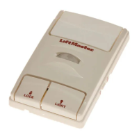
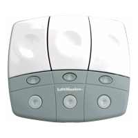
The two and three garage door multi-function control panel
is designed to replace multiple door control buttons on
LiftMaster Security✚ garage door openers. It can be used as
a replacement stand alone unit or in conjunction with the
original factory door control buttons. Never connect more
than two control panels or door control buttons to any one
garage door opener.
INSTALLATION
Product may be mounted directly to wall board or, for pre-wired
installations (as in new home construction), it may be mounted to
a single gang box. In either case the installation surface must
be smooth and flat.
The door orientation goes from left to right, and wiring is as
follows:
• Left Door – Door A
Wire white wire to White-1 and red/white wire to Red-1
• Middle Door – Door B
Wire white wire to White-2 and red/white wire to Red-2
Note: Model 902 LM will only have A and C terminals.
• Right Door – Door C
Wire white wire to White-3 and red/white wire to Red-3
NOTE: If replacing existing wall controls, labeling the existing
wires with masking tape might be helpful (i.e. Door A, Door B,
Door C).
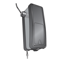
1. Strip 7/16" of insulation from one end of bell wire and connect
to the corresponding two screw terminal on back of door
control by color. Figure 1. White to WHITE and red/white to
RED. Be careful to wrap the exposed wire tightly around the
screw and tighten. The exposed wire must not come into
contact with exposed solder points. The Mylar insulator is
there to prevent this from happening. Do not remove this
insulator.
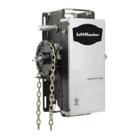
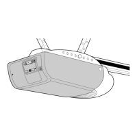
2. Run bell wire up wall and across ceiling to motor unit. Use
insulated staples to secure wire in several places. Do not
pierce wire with a staple, creating a short or open circuit.
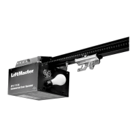
3. Strip 7/16" of insulation from opposite end of bell wire.
Connect bell wire to the Quick-Connect™ terminals located on
garage door opener as follows: white to white and white/red to
red. Figure 5.
NOTE: The door control button may stick if the door control is
not mounted on a smooth surface. If a click is not heard when
pressing the door control button, loosen the two mounting
screws or relocate the door control to a smoother surface.
After installation, an orange indicator light behind the door
control buttons will indicate proper connection. If not lit, the Lock
and Light features will not function (reverse wires to correct).