82
P/N 115109 - Direct Vent Option Installation Instructions
Electrical Connections for the Optional Direct Vent Fan
(Supplied By Champion)
Champion Vent Fan Terminal Block
120VAC/50-60/1
Terminal
Block
L
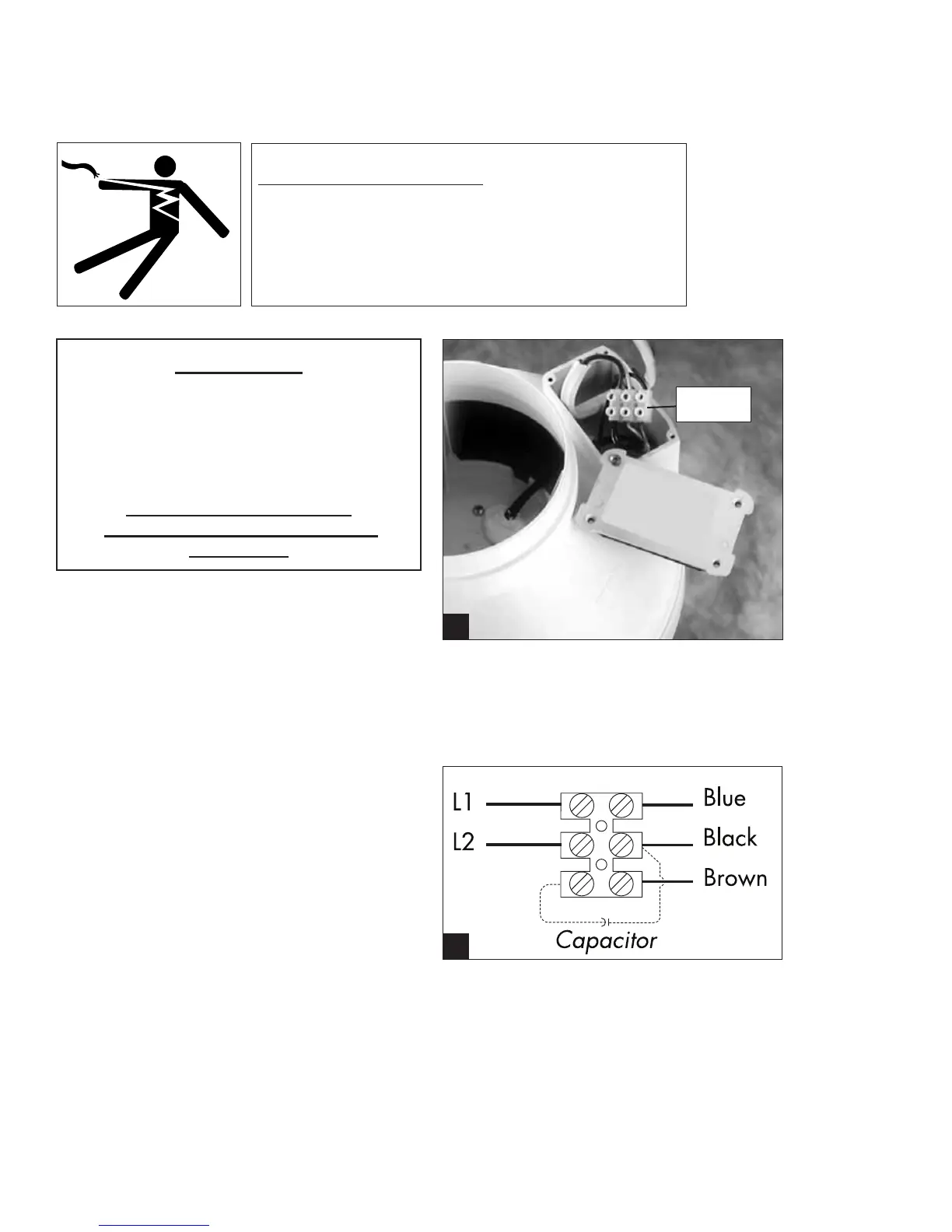
Champion Vent Fan Terminal Block
Wiring Diagram
M
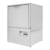
! IMPORTANT !
Electrical installation must be performed by
qualied personnel in accordance with
all local codes and regulations or in the
absence of local codes then the National
Electrical Code.
DO NOT CONNECT POWER
UNTIL THE FAN IS COMPLETELY
INSTALLED.
1. The Champion supplied vent fan is
120VAC/50-60/1.
2. Incoming power is connected to the
vent fan terminal block located in the
vent fan junction box on the side of the
vent fan assembly. (See Figure L).
3. Grounding of the vent fan is not
required because the fan motor is
isolated within the vent fan plastic
housing.
4. Connect the 120VAC power supply
to the vent fan terminal block.
(See Figure M).
5. If the 12 ft. [3.7 m] vent fan cable
supplied with the direct vent fan
control box is not long enough for the
installation, the installer may replace
the cable with a longer cord of the
sameelectricalspecications.
6. Refer to Figure N on the next
page for the direct vent fan control box
cable wiring diagram.
WARNING:
Electrocution or serious injury may result when
working on an energized circuit.
Disconnect power at the main breaker or service
disconnect switch before working on the circuit.
Lock-out and tag the breaker to indicate that work is
being performed on the circuit.

 Loading...