7
TWO STAGE AIR COMPRESSORS - MODEL PL70A
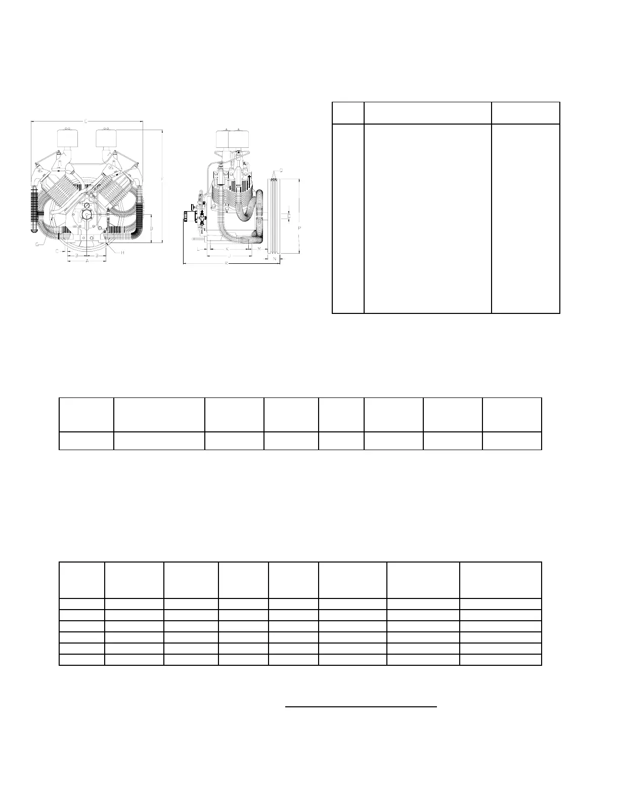
DIMENSIONS
ITEM PL70A
A
B
C
D
E
F
G
H
J
K
L
M
N
O
P
Q
R
Base-Width
Bolt Down-Width
(from center line)
Bolt Down to Edge
Base to Crank Ctr
Overall Width
Overall Height
HP Exhaust Opening
Bolt Down Hole Dia.
Base-Depth
Bolt Down Depth
Bolt Down to Edge
Bolt Hole to Wheel (Max.)
Flywheel Width
Crank Diameter
Flywheel Diameter
Flywheel Grooves
Overall Depth
12-7/8”
5-11/16”
3/4”
8-3/16”
33”
33-9/16”
1-1/4NPT
9/16”
13-1/4”
11-1/4”
1”
5-3/4”
3-1/2”
2-1/4”
22”
3VB
28-9/16”
NOTE:
Flywheel Rotation – Clockwise when viewed
from front, flywheel to rear.
SPECIFICATIONS
MODEL BORE & STROKE
(INCH)
NO. of
CYLINDERS
OIL
CAPACITY
(QTS)
WEIGHT
(LBS)
MAXIMUM
PRESSURE
(PSIG)
CU
FT./REV.
MIN./MAX.
RPM.
PL70A 6-1/4" & 3-1/4" x 4" 4 6-1/3 450 250 .142 425/1000
Standard units are set up for 175 PSIG operation. High pressure units are set for the higher 250 PSIG range and
come with the special tanks, pressure switches, pressure relief valves, pulleys and pilot valves. To determine the
pressure setting of a particular compressor check the pressure setting decal located on the air tank.
Note that 175 PSIG units cannot be converted to safely operate at pressures above 200 PSIG unless all the above
mentioned components including the air tank are replaced with 250 PSIG rated items. Refer to parts list for
applicable part numbers.
PERFORMANCE
PUMP
OUTPUT
PRESS.
PSIG
MOTOR
H.P.
PUMP
RPM
DISPL.
CFM
COOLING
AIR FLOW
CFM
HEAT
REJECTION
BTU/HR
APPROX.
PULLEY O.D.,
INCHES
PL70A 175 20 655 93.0 2195 44
700 8.35
PL70A 175 25 770 109.4 2580 55
970 9.75
PL70A 175 30 890 127.8 2980 67
160 11.35
PL70A 250 20 545 77.4 1825 44
700 6.75
PL70A 250 25 660 93.7 2195 55
970 8.35
PL70A 250 30 770 109.4 2580 67
160 9.75
All data is based on 1725 RPM electric motors as a power source.
Pulley Dia. (approx.) = Compressor RPM x Flywheel Dia.
Motor or Engine RPM
C-331-
(Ref. Drawing)