8
INSTALLATION
WARNING
Do not operate unit if damaged during shipping, handling or use. Operating unit if damaged may result in
injury.
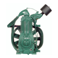
1. Permanently installed compressors must be located in a clean, well ventilated dry room so compressor
receives adequate supply of fresh, clean, cool and dry air. It is recommended that a compressor, used for
painting, be located in a separate room from that area wherein body sanding and painting is done. Abrasive
particles or paint, found to have clogged the air intake filters and intake valves, shall automatically void
warranty.
2. Compressors should never be located so close to a wall or other obstruction that flow of air through the fan
blade flywheel, which cools the compressor, is impeded. Permanently mounted units should have flywheel at
least 12" from wall.
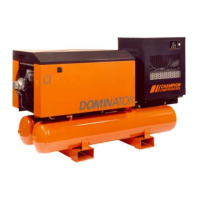
3. Place stationary compressors on firm level ground or flooring. Permanent installations require bolting to floor.
Bolt holes in tank or base feet are provided. Before bolting or lagging down, shim compressor level. Avoid
putting a stress on a tank foot by pulling it down to floor. This will only result in abnormal vibration, and
possible cracking of air receiver. It is recommended that unit be set on optional vibro-isolator pads. Tanks
bolted directly to a concrete floor without isolators will not be warranted against cracking. Champion vibro-
isolators or approved equivalent must be installed for extended warranty to apply to ASME receivers.
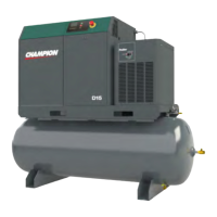
4. If installing a bare pump, or base mounted unit, make certain the pressure limiting controls are properly
installed and operational. The PL model pump is supplied with a pilot valve, but a pressure switch must be
provided by customer for start/stop operation. The hydraulic unloading system requires a control air pressure
line from the air receiver to be connected to the pilot valve fitting on the pump.
DANGER
Do not install isolating valves between compressor outlet and air receiver. This will cause excessive
pressure if valve is closed and cause injury and equipment damage.
WARNING
Always use an air pressure regulating device at the point of use. Failure to do so can result in injury or
equipment damage.
CAUTION
• Do not install in an area where ambient temperature is below 32 degrees F or above 100 degrees
F.
• Do not install unit in an area where air is dirty and/or chemical laden.
• Unit is not to be installed outdoors.
ELECTRICAL POWER SUPPLY
It is essential that he power supply and the supply wiring are adequately sized and that the voltage
correspond to the unit specifications. Branch circuit protection must be provided at installation a
specified in the National Electrical Code.
All wiring should be preformed by a licensed electrician or electrical contractor. Wiring must meet
applicable codes for area of installation. The table gives recommended wire sizes based on the
1999 NEC.
WIRE SIZE (AWG) – 75°C COPPER – 30°C AMBIENT
MOTOR
HP
200/208V 230V 460V 575V
20 3
0
4
1
8
6
10
6
25 1
000
2
00
6
4
8
6
30 0
0000
1
000
6
3
8
4
Values in ( ) for Duplex Unit w/one incoming power line to both motors.