100-00-4 Overview
100-00-3
Instruction and Operation
Illustration Indication
The testing diagram shows the required
measurement or test in some certain testing
procedure.
The typical test diagram is suitable for the use of a
voltage gauge and an ampere meter.
When a signal diagram shows the multi-step test,
the solid line draws the conducting wire until the
multi-step measured conducting wire branch points,
and the conducting wire of multi-step measuring
points after the branch point should adopt the dotted
line.
The double circle testing pin is used for indicating
the disaster box type instrument. The testing pin
should be labeled with pin number.
Examples
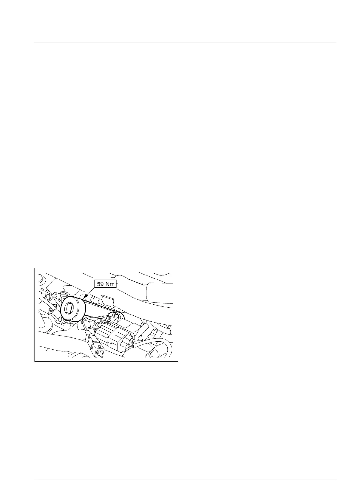
When the special tool is required, its figure and use
method will be provided, or the tool number will be
listed. The preset torque value will be given at the
corresponding position in the procedures.
 Loading...