15
L max = 14 m 2.24 FF - 1.24 FF
L max = 11 m 2.31 FF
L max = 15 m 2.24 FF - 1.24 FF
L max = 12 m 2.31 FF
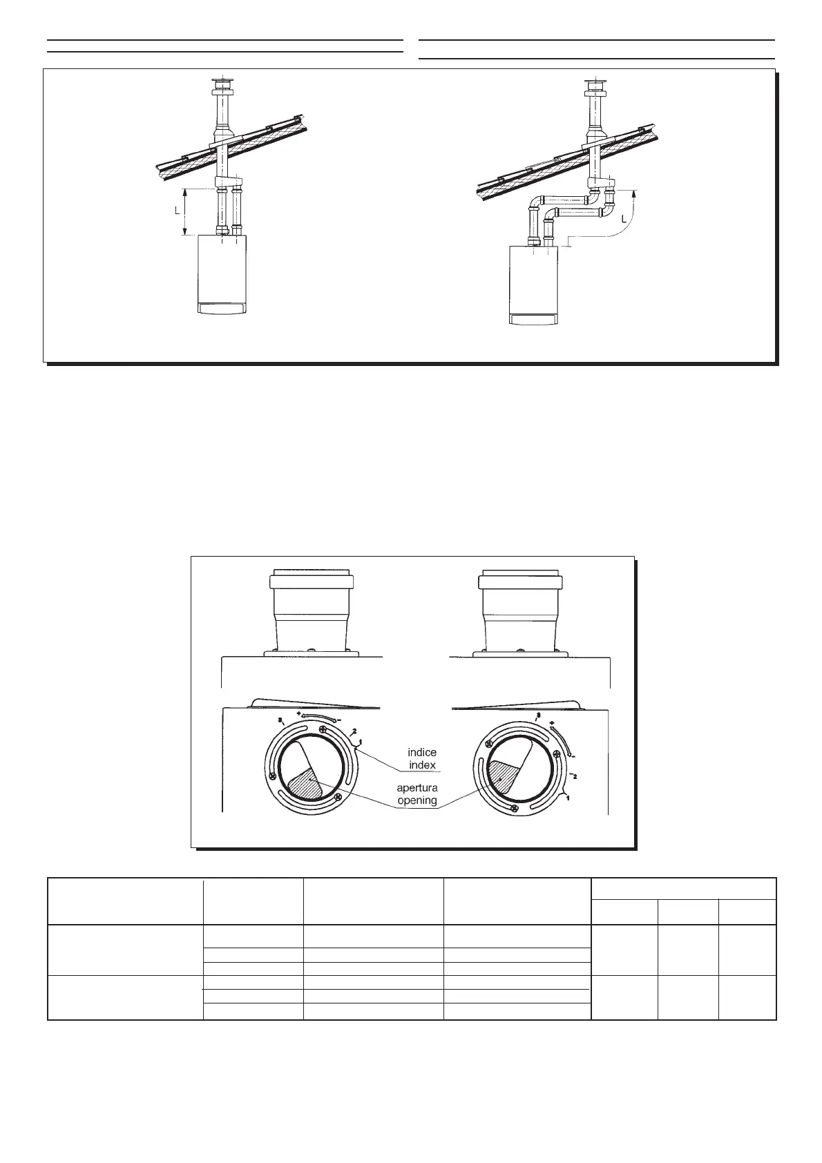
Separated vertical flue terminals installation options
Επιλογές εγκατάστασης ξεχωριστών κάθετων καπνοδχων
Important: if fitting a single exhaust flue duct, ensure it is adequately
insulated (e.g.: with glass wool) wherever the duct passes through building
walls.
For detailed instructions concerning the installation of fittings refer to
the technical data accompanying the fittings.
Split flue air control adjustment
The adjustment of this control is required to optimise performance and com-
bustion parameters. The air suction coupling which may be mounted on the
left or right of the flue duct can be rotated to adjust excess air according to
the total length of the flue and
intake ducts for the combus-
tion air.
Turn this control clockwise
to decrease excess combus-
tion air and anticlockwise to
increase it.
To improve optimisation a
combustion product ana-
lyser can be used to meas-
ure the CO
2
contents of the
flue at maximum heat out-
put, gradually adjusting air
to obtain the CO
2
reading in
the table below, if the analy-
sis shows a lower value.
To properly install this de-
vice, also refer to the tech-
nical data accompanying the
fitting.
0003170100
0003170200
Figura 9
εικνα 9
sx
dx
0004190300
(*) CO2%
ΜΟΝΤΕΛΟ ΛΕΒΗΤΑ (L1+L2) MAX ΘΕΣΗ ΡΥΘΜΙΣΤΗ ΧΡΗΣΗ ∆ΙΑΦΡΑΓΜΑΤΟΣ
BOILER MODEL CONTROL POSITION DIAPHRAGM USE
G.20 G.30 G.31
0÷15 1 —
15÷30 2 — 6 7 7
30÷40 3 —
0÷2 3 ναι -
YES
2÷10 2 χι -
NO
7—8,5
10÷25 3 χι -
NO
- Το διάφραγµα είναι σχεδιασµένο για χρήση µε το µοντέλο INITIA
SUPER 2.31 FF µνο. Τοποθετήστε αυτ το εξάρτηµα στην υποδοχή
του εισαγµενου αέρα, µνο εάν το συνολικ µήκοσ των καπνοδχων
και αγωγών αέρα δεν ξεπερνά τα 2 µέτρα.
(*) The diaphragm is designed for use on 2.31 model only. Position this
component (supplied with the boiler) inside the air intake sleeve only if
the total lengths of the exhaust and intake sections do not exceed 2 metres.
2.31 FF
1.24 FF - 2.24 FF
Προσοχή: Αν εγκατασταθεί απλή καπνοδχοσ, βεβαιωθείτε τι είναι
καλά µονωµένη (π.χ. πετροβάµβακασ) ταν περνάει απ τοίχουσ.
Για λεπτοµερείσ περιγραφέσ τησ εγκατάστασησ των εξαρτηµάτων
συµβουλευτείτε τισ οδηγίεσ που τισ συνοδεύουν.
Ξεχωριστή ρύθµιση καυσαερίων - αέρα
Η ρύθµιση αυτή απαιτείται για τη βέλτιστη λειτουργία τησ καύσησ. Η
σύζευξη του αέρα αναρρφησησ που µπορεί να είναι στο αριστερ ή
δεξί µέροσ τησ καπνοδχου, περιστρέφεται για να ρυθµίσει τον
επιπλέον αέρα σύµφωνα µε το ολικ µήκοσ τησ καπνοδχου και του
αεραγωγού για τον αέρα καύσησ.
Στρίβοντασ το ρυθµιστή δεξιστροφα, µειώνεται ο αέρασ καύσησ και
αριστερστροφα
αυξάνεται.
Για καλύτερα
αποτελέσµατα, ένασ
αναλυτήσ καυσαερίων
µπορεί να χρησιµοποιηθεί
για µέτρηση του CO2.
Ρυθµίζοντασ τον αέρα
πρέπει να επιταχύνουµε
τισ τιµέσ που
αναγράφονται στον
παρακάτω πίνακα, αν ο
µετρητήσ δείχνει
χαµηλτερεσ τιµέσ.
Για να χρησιµοποιηθεί
σωστά ο µετρητήσ,
συµβουλευτείτε τισ
τεχνικέσ οδηγίεσ που
συνοδεύουν το εξάρτηµα.