33
INSTALLER Section (en)
7698967.01 (1-01/18)
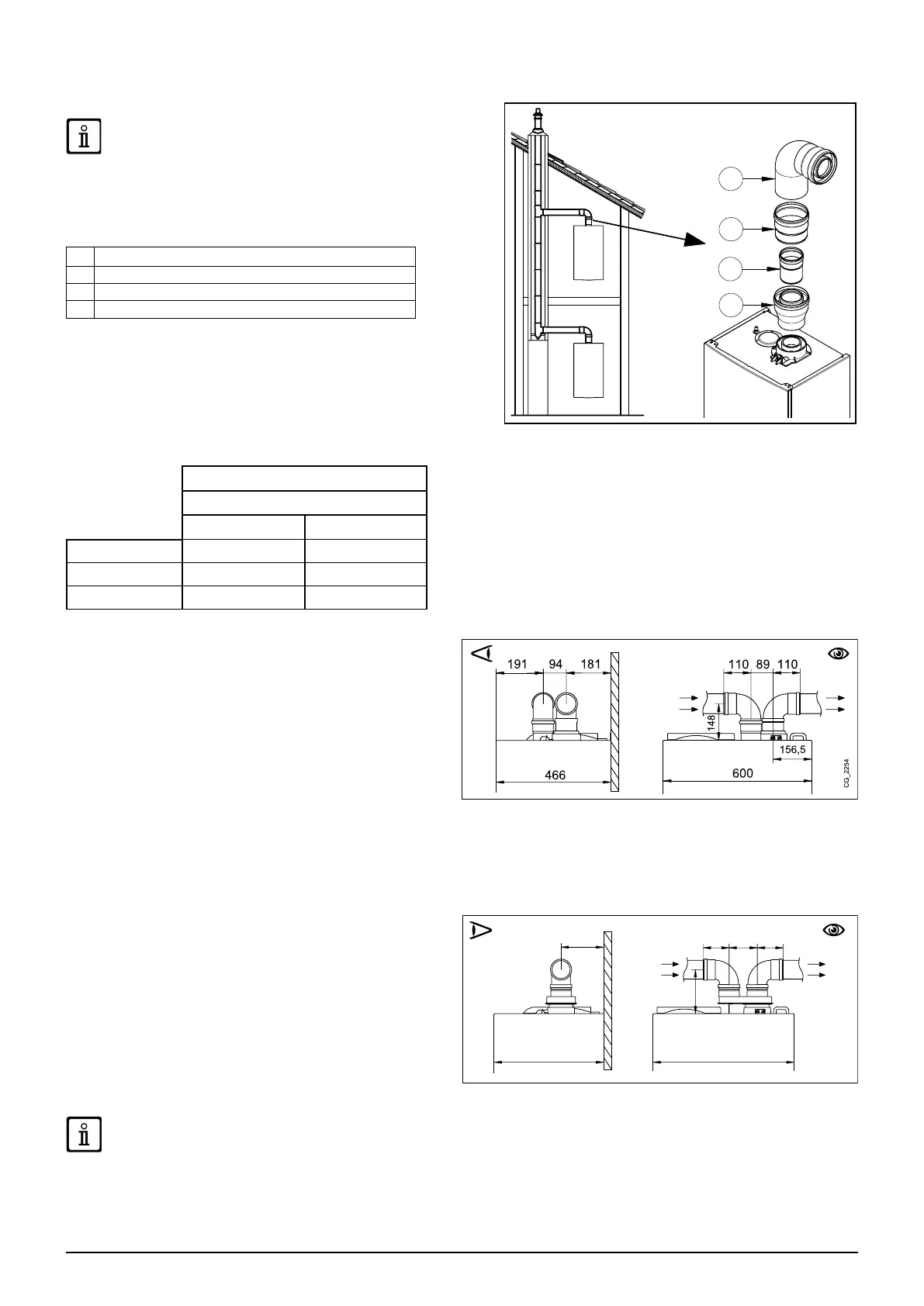
10.1.1 C43P EXHAUST TYPE
Collective positive pressure ue pipe for sealed chamber boilers
This Kit may only be used with natural gas boilers (G20)
In order to connect the boiler to a C43P collective ue pipe, the
nonreturn valve is required.
The sizing of the ue pipe is dened by the conduit supplier in
accordance with EN 13384-2.
1 90° elbow Ø 80/125 mm
2 Duct Ø 80/125 mm
3 Non-return valve Ø 80 mm
4 Adaptor Ø 60/100 -> 80/125 mm
FAN SPEED ADJUSTMENT (MINIMUM POWER)
For this type of installation, it will be necessary to modify parameter
P60 (9524) (fan speed at minimum power) of the boiler electronic
board based on the maximum positive pressure of the pressurised
ue duct. See the table below for the values.
To access parameter P60 (9524) and modify the speed value, proceed
as described in chapter 14.
P60 (9524) - Revs/min (rpm)
Max chimney pressure
10 mm H
2
O 15 mm H
2
O
Boiler model
G20 G20
3.25 2470 2700
3.33 2520 820
10.2 SEPARATE DUCTS
This type of installation makes it possible to discharge exhaust
fumes both outside the building and into single ue ducts.
Comburent air can be drawn in at a different location from that
of the ue terminal. The accessory splitting kit comprises a ue
duct adaptor (80) (B) and an air duct adaptor (A). For the air
duct adaptor, t the screws and seals previously removed from
the cap.
The 90° bend is used to connect the boiler to the inlet and
outlet ducts, adapting them to various requirements. It can also
be used as a supplementary curve combined with a duct or a
45° bend.
• A 90° bend reduces the total duct length by 0.5 metres.
• A 45° bend reduces the total duct length by 0.25 metres.
• The rst 90° bend is not included when calculating the maximum available length.
SINGLE SPLITTING KIT (ALTERNATIVE ACCESSORY)
For special installations of the fumes inlet/outlet ducts, the
single splitting kit (C), supplied as an accessory, can be used.
This accessory, in fact, can be used to move the inlet and outlet
in any direction. This type of installation makes it possible to
discharge exhaust fumes both outside the building and into
single ue ducts. Comburent air can be drawn in at a different
location from that of the ue terminal. The splitting kit is xed
to the boiler turret (100/60 mm) and allows the comburent air
and outlet fumes to enter/leave the two separate ducts (80
mm). For further information, read the assembly instructions
supplied with the accessory.
SOME OUTLET DUCT INSTALLATION EXAMPLES AND THEIR RELATIVE MAXIMUM LENGTHS ARE SHOWN IN ANNEX
"SECTION" D AT THE END OF THIS MANUAL.
AB