7698967.01 (1-01/18) 40
INSTALLER Section (en)
BOILER CONTROL PANEL PARAMETERS
P62 - Unit of measurement (1=bar, °C – 2=PSI, °F) - 1
P63 - Control panel operation: (1=central, 0=local) - 1
P64 - Software version
-
xx
* see “Accessories not included in supply”
xx: the value depends on the software version xxx: the value depends on the type of boiler
(a): parameters read on the front boiler panel (xed control panel) (b): parameters read on the Remote Control
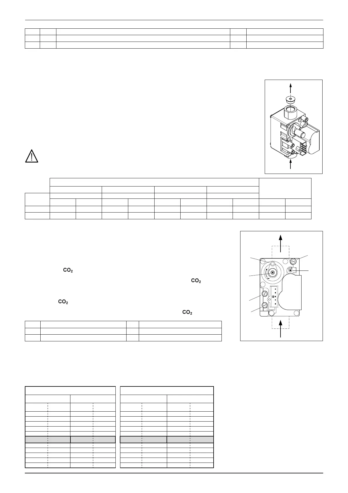
15. GAS CONVERSION METHODS
Only an Authorised Technical Assistance Service can convert boiler operation from G20 to G31 gas or
vice-versa. To calibrate (and select the correct nozzle), see TABLE 1 and proceed as follows:
• Replace the nozzle of the gas valve, supplied as a kit, as illustrated in the gure to the side;
• Set the board parameters, fan revs (rpm);
• Enable the calibration function (see previous section);
• Calibrate the gas valve as described in section 15.1 points 1 and 2.
To access the parameters indicated in table 1, see the procedure described in section 14.
When the gas change is completed the boiler data plate must be amended to indicate the new gas
data.
TABLE 1: FAN SPEED PARAMETERS AND GAS NOZZLE
PARAMETERS - rpm
Ø GAS NOZZLE (mm)
P60 (a) P30 (a) P61 (a) P59 (a)
Boiler
model
Min. power Pmax heating Pmax DHW Ignition power
G20 G31 G20 G31 G20 G31 G20 G31 G20 G31
3.33 1600 1500 4800 4500 6500 6100 3000 2500 7,0 4,6
3.25 1400 1400 4200 4000 6400 6100 3000 3000 5,6 3,8
(a) value read on the boiler front panel display to multiply x 10 (e.g.: 150 corresponds to 1500 rpm).
15.1 GAS VALVE CALIBRATION
To calibrate the gas valve, enable the calibration function as described in section 15 and
carry out the following operations:
1) Calibrating MAXIMUM heat output.
Check that the /O
2
measured on the ue duct, with the boiler operating at maximum
heat capacity, matches that indicated in table 1B. If it does not, turn the adjustment screw
(V) on the gas valve. Turn the screw clockwise to decrease the level of and clockwise
to increase it.
2) Calibrating REDUCED heat output
Check that the /O
2
measured on the ue duct, with the boiler operating at minimum heat
capacity, matches that indicated in table 1B. If it does not, turn the adjustment screw (K)
on the gas valve. Turn the screw clockwise to increase the level of and anticlockwise
to decrease it.
Pi Gas supply pressure tap PI Airtight chamber pressure signal
Pout Burner gas pressure tap V Gas ow adjustment screw
P OFFSET measurement pressure tap K OFFSET adjustment screw
For each CO
2
/O
2
value found at the maximum thermal capacity, there is a range of CO
2
/O
2
values at the minimum thermal capacity
shown in the same line of the table.
The nominal calibration values of the gas valve for each type of gas used are shown in bold.
The CO
2
/O
2
values are with the cover closed.
The maximum permitted CO value must be lower than 250 ppm.
TABLE 1B
G20 G31
CO
2
(%) O
2
(%) CO
2
(%) O
2
(%)
P max P min P max P min P max P min P max P min
9,2 8,7÷9,1 4,5 4,7÷5,4 10,7 10,1÷10,6 4,6 4,8÷5,5
9,1 8,6÷9 4,7 4,8÷5,6 10,6 10÷10,5 4,8 4,9÷5,7
9 8,5÷8,9 4,8 5÷5,7 10,5 9,9÷10,4 4,9 5,1÷5,8
8,9 8,4÷8,8 5 5,2÷5,9 10,4 9,8÷10,3 5,1 5,2÷6
8,8 8,3÷8,7 5,2 5,4÷6,1 10,3 9,7÷10,2 5,2 5,4÷6,1
8,7 8,2÷8,6 5,4 5,6÷6,3 10,2 9,6÷10,1 5,4 5,5÷6,3
8,6 8,1÷8,5 5,6 5,7÷6,5 10,1 9,5÷10 5,5 5,7÷6,4
8,5 8÷8,4 5,7 5,9÷6,6 10 9,4÷9,9 5,7 5,8÷6,6
8,4 7,9÷8,3 5,9 6,1÷6,8 9,9 9,3÷9,8 5,8 6÷6,7
8,3 7,8÷8,2 6,1 6,3÷7 9,8 9,2÷9,7 6,0 6,1÷6,9
8,2 7,7÷8,1 6,3 6,5÷7,2 9,7 9,1÷9,5 6,1 6,4÷7,1