35
The field of application is limited to industrial frequencies
(15 Hz... 70 Hz)
■■
■■
■ Implementation
This function is accessible in AC current measurement only,
after selection of the MIN/MAX mode.
Action Display Comments
Press 0.5 P then the value
the yellow for rms Enter the function
key corresponding
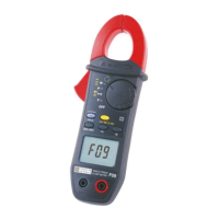
out F Signal frequency
< 15 Hz or > 70 Hz
Press on 1P-2,5P-5P-10P-0,5P
HOLD key ↑ Consultation of values
then press with each time rms (computed on
successively the rms value of consecutive periods )
the yellow corresponding
key alternately
Short pressure Return to values Exit from the function
on the MIN, MAX or PEAK return to MIN/MAX mode
MIN/MAX key
■■
■■
■ Characteristics
- Accuracy: 5% +0.5 A
- Capture time: 10 periods of the signal frequency (200 ms
at 50 Hz)
- Range for use: ≥ 5 A peak for the first period of the signal
3.8 Power measurement (W var VA)
1. Connect the measurement leads to the instrument’s
terminals, complying with the polarities indicated: red lead
on the “+” terminal and black lead on the “COM” terminal.
2. Set the rotary switch to position “W”(single phase
measurement).
3. Make a long press on the yellow key for measurement on
balanced 3 phases system.
4. Connect the clamp on the system selected for power
measurement, complying with the following instructions:
SINGLE PHASE SYSTEM
- Connect the measurement cables for voltage
measurement, red cable on phase, black cable on neutral.
- Clamp the conductor carrying the current to be measured,
check for proper closing of the jaws and for foreign bodies
in the gap.
BALANCED 3 PHASES SYSTEM
- Connect the measurement cable for voltage
measurement, red cable on phase 1, black cable on
phase 2 (U
12
measurement).
- Clamp the conductor of phase 3 (I
3
measurement).