36
36
Nota : same results are achieved with the following couples
of measurement : U
23
with I
1
and U
31
with I
2
.
In both cases the “
➭
“ arrow on the jaws, must be directed
in the direction of power circulation from the source to the
load. In which case:
- the “+” sign corresponds to power consumed by the load.
- the “-” sign corresponds to power supplied by the load.
■■
■■
■ Specific reference conditions
PF = 1; I ≥ 2 A; U ≥ 10 V
■■
■■
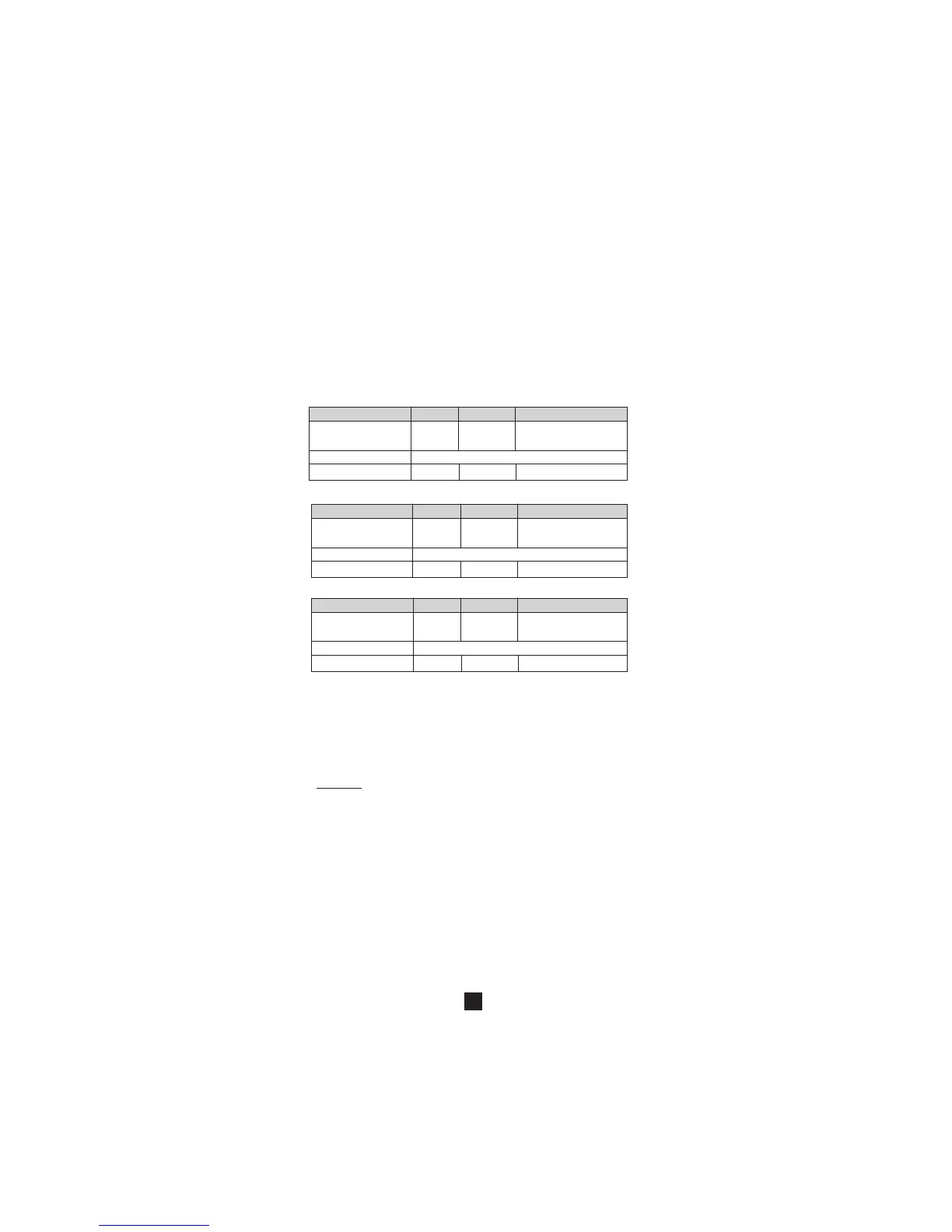
■ Active power measurement characteristics
Display range 4000 W 40 kW 400 kW
Measuring range (2) 5 to 4,00 kW to 40,0 kW to
3999 W 39,99 kW 240,0 kW -399,9kW (1)
Accuracy (3) 2% L + 1 pt
Resolution 1 W 10 W 100 W
■■
■■
■ Reactive power measurement characteristics
Display range 4000 var 40 kvar 400 kvar
Measuring range (2) 5 to 4,00 kvar to 40,0 kvar to
3999 var 39,99 kvar 240,0 kvar -399,9kvar (1)
Accuracy (3) 2% L + 1 pt
Resolution 1 var 10 var 100 var
■■
■■
■ Apparent power measurement characteristics
Display range 4000 VA 40 kVA 400 kVA
Measuring range (2) 5 to 4,00 kVA to 40,0 kVA to
3999 VA 39,99 kVA 240,0 kVA -399,9kVA (1)
Accuracy (3) 2% L + 1 pt
Resolution 1 VA 10 VA 100 VA
(1) the scale is limited to 240 kW (kvar, kVA) in one-phase
(600 V x 400 A) and 399.9kW (kvar kVA) in 3 phases system.
Above this value, the display indicates +OL or -OL depending
on the sign of the power.
(2) if the power value is < 5 W or if the voltage or current
values are respectively < 0.15 V or < 0.15 A, 0 is displayed.
(3) The measurement accuracy is affected by an instability
linked to current measurement of approximately 0.1 A.
Example: for a power measurement performed at 10 A, the
instability of the measurement will be 0.1 A/10 A, or 1%.
■■
■■
■ MIN/ MAX Mode:
- Accuracy: same as previous table +0.3% L
- Capture time: 100 ms typ. (every 400 ms)
3.9 Power factor calculation (PF)
With the clamp configured in power measurement (switch
on position W) and correctly connected (see § 3.8), perform
a short press on the yellow key: the power factor is displayed.
The power factor is, by definition, an unsigned quantity,
however, a sign is displayed showing whether the charge is
inductive (“+” sign) or capacitive (“-” sign). This sign is
significant only in the case of slightly distorted signals (i.e. 3
switches to zero over 1 period).