38
38
- Acceptable amplitude imbalance rate: 20%
- Acceptable voltage harmonic distortion: 10%
■■
■■
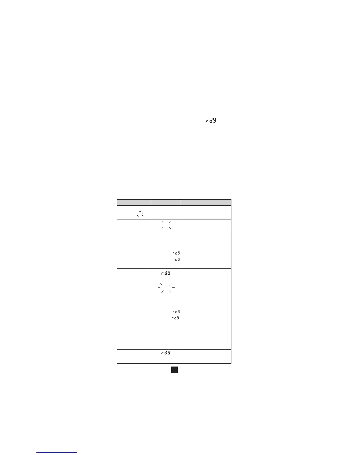
■ Running of phase rotation direction detection
sequence
Note 1:
In the following table, display of the symbol " " refers
systematically to the beginning of sequence
Note 2:
The sequence of the following table is described using:
- L1 on terminal “COM”
- L2 then L3 on terminal “+”
The same result is obtained if:
- L2 on terminal “COM” , L3 then L1 on terminal “+”
or:
- L3 on terminal “COM” , L1 then L2 on terminal “+”
Note 3:
The measurement principle is based on a certain frequency
stability and practically sinusoidal signals (THD < 10%).
This excludes in particular measurement on power
generators whose spin stabilisation system is too weak to
ensure adequate frequency stability.
Action Display Comments
Switch on Enter the function
the position
Press rEF The unit is ready to detect
the yellow key the reference period
Cable connected after 10 seconds maximum
black on L1 and result is one of the 3 following
contact displays
red cable on L2 opposite:
Err V (2 s) then → if voltage < 50 V
Err V (2 s) then → if nominal freq. ≠ 50 Hz or 60 Hz
rEF OK → if reference period correct
Red cable contact The unit determines the period
on L3 (less than measurement, the following
10 seconds after messages may be displayed
leaving L2) (after 10 s max) :
MEAS → determination of period
for measurement in progress
→ contact on L3 a was performed
too late (more than 10 s
after display rEF OK)
Err V (2 s) then → voltage incorrect
Err V (2 s) then → frequency incorrect
Err → determination of phase
direction impossible
1.2.3 → direct direction of phase
rotation
3.2.1 → reverse direction of phase
rotation
Press yellow key Return to beginning of sequence
(valid at all times in the
sequence)