RM23712 TPS
50
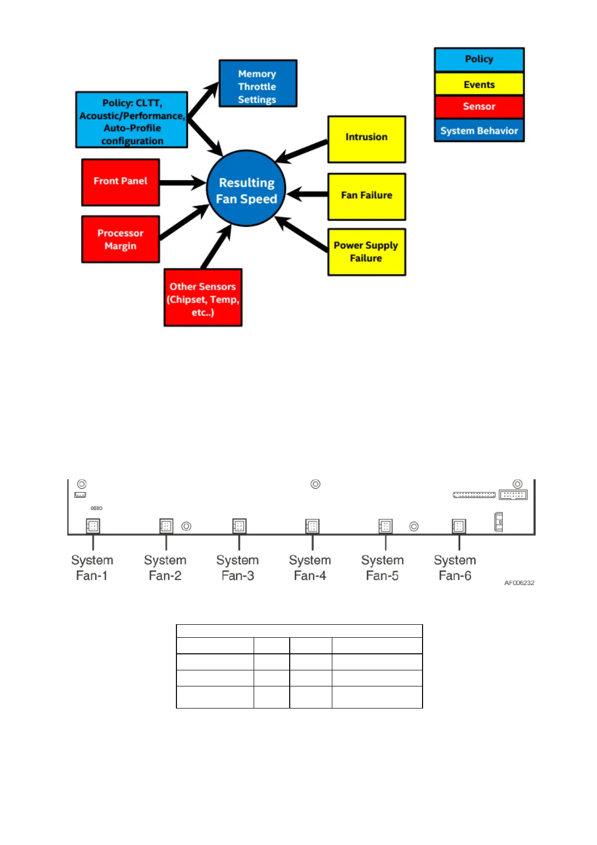
Figure 24.Fan Control Model
4.3 System Fans
Six 60 x 38mm system fans, and dedicated fans for the installed power supply modules provide the
primary airflow for the system.
The server board is capable of supporting up to a total of six system fans. On the server board, each
system fan includes a pair of fan connectors. a 2x3 pin connector to support a single rotor hot swap
fan assembly.
Figure 25.System Fan Connector Locations
Table 41. System Fan Connector Pin-out
The system fan assembly is designed for ease of use and supports several features.
The entire fan assembly can be removed making it easier to service other features of the
system
Each individual fan is hot-swappable
Each fan is blind mated to a matching 6-pin connector located on the server board