EasyManua.ls Logo

Chenbro RM23712 - Figure 36. 12 G Mini SAS HD 12 Port Backplane - Rear View; Table 44.Connector Pin-Out - Mini SAS HD Backplane

Default Icon
109 pages
To Next Page IconTo Next Page
To Previous Page IconTo Previous Page
Loading...
RM23712 TPS
58
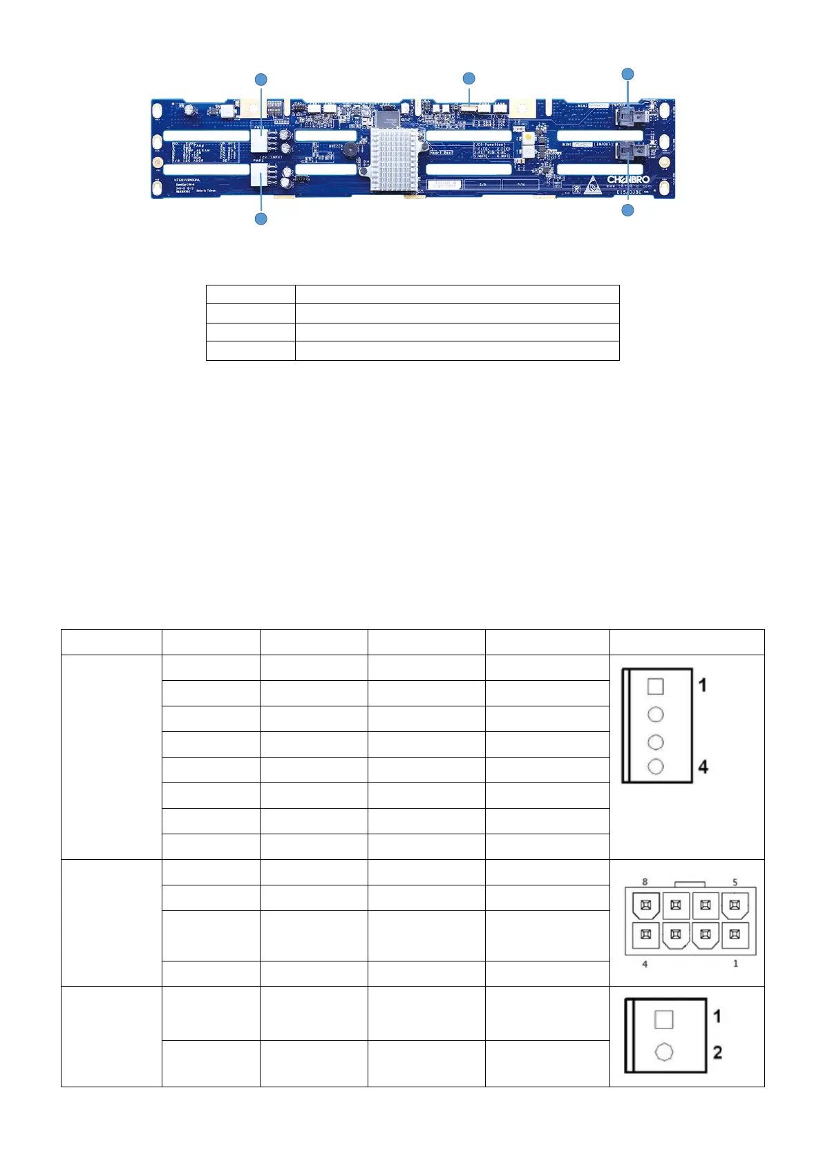
Figure 36. 12G Mini SAS HD 12 Port Backplane rear view
Label
Description
A
Power connector
B
SAS/SATA Ports 0-3 Mini-SAS HD cable connector
C
I2C connector
A Power Connector The backplane includes a 2x4 connector supplying power to the backplane.
Power is routed to the backplane via a power cable harness from the Power Supply Modules.
B Multi-port Mini-SAS Cable Connector The backplane includes one multi-port mini-SAS cable
connector providing data signals for four SAS/SATA drives on the backplane. A cable can be routed
from matching connectors on the server board or add-in SAS/SATA RAID cards.
C I2C Cable Connector The backplane includes a 1x3 cable connector used as a management
interface to the server board.
Table 44.Connector Pin-out Mini SAS HD Backplane
Connector
Pin Number
Pin Definition
Input/output
Description
Drawing
Power
Connector
(JP01&JP02)
1
GND
Power Output
Power GND
2
GND
Power Output
Power GND
3
GND
Power Output
Power GND
4
GND
Power Output
Power GND
5
+12V
Power Output
Power +12V
6
+12V
Power Output
Power +12V
7
+12V
Power Output
Power +12V
8
+12V
Power Output
Power +12V
Fan
Connector
(JF2~JF5)
1
GND
Power Output
Power GND
2
+12V
Power Output
Power +12V
3
TACHO
Input
FAN Sensor
signal
4
PWM
Output
FAN PWM signal
Power FAIL
ALARM
Connector
(JC7)
1
GND
Power Output
Power GND
2
PSU Alarm
Input
Fail signal Input
A
B
B
C
A
A
C
B
B

Table of Contents