Installation Instructions AVSFSS
11
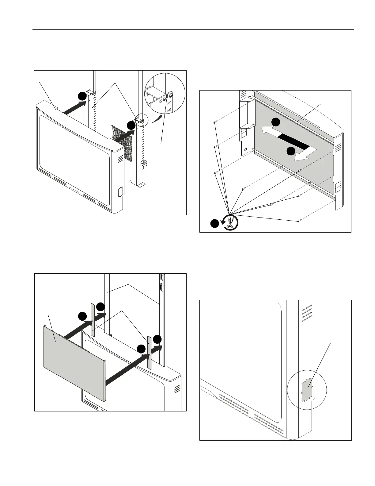
Covers Installation
1. Place base cover (C) onto bottom uprights (G) and slide into
slots on top of uprights. (See Figure 19)
Figure 19
2. Install two magnetic tape strips (E) onto top uprights (B) by
removing adhesive cover to permanently secure them to
uprights. Strips (E) should be located approximately 1"
above base cover (C). (See Figure 20)
3. Place mid cover (K) onto two magnetic strips (E). (See
Figure 20)
Figure 20
Aesthetic Cover Removal/Replacement/
Adjustment
1. Remove eight Phillips screws holding aesthetic cover inside
base cover (C) and spanning bracket. (See Figure 21)
2. Remove aesthetic cover from base cover by sliding it first to
one side and then out. (See Figure 21)
3. (Optional) Replace with alternative cover (not included) and
secure with removed screws.
NOTE: If cover becomes wrinkled or loose, loosen bottom four
screws as needed, tighten the fabric and the re-tighten
screws.
Figure 21
Cover Knockout Usage (Optional)
1. Remove knockouts on base cover (C) as desired for cable
management or to install control boxes. (See Figure 22)
NOTE: Holes around knockout box may be used to secure
boxes or accessories to base cover using appropriate
hardware.
Figure 22
(C)
1
1
(G) x 2
slot
2
2
3
3
(E) x 2
(K)
(B) x 2
x 8
1
2
2
spanning
bracket
knockout