AVSFSS Installation Instructions
10
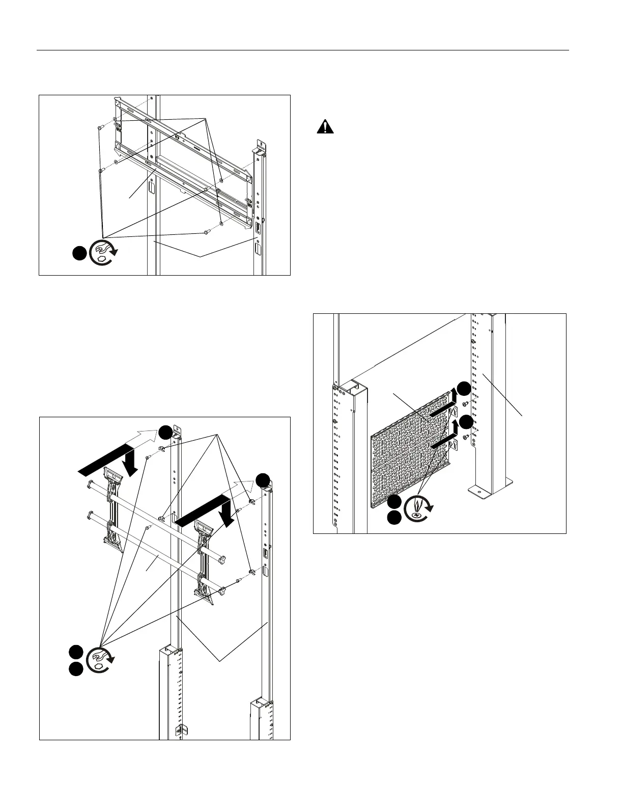
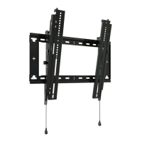
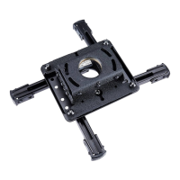
1. (For RMF2/RLF2/RXF2) Use four 1/4-20 x 1/2" hex head
cap screws (R) and four 5/16 washers (T) to secure main
assembly of RLF2 onto top uprights (B). (See Figure 16)
Figure 16
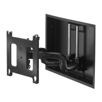
2. (For LTM1U/LSM1U/MTM1U/MSM1U) Loosely install
four 1/4-20 x 1/2" hex head cap screws (R) and four slotted
washers (included with LTM1U) into top holes of top
uprights (B). (See Figure 17)
3. (For LTM1U/LSM1U/MTM1U/MSM1U) Use teardrop
holes to place LTM1U main assembly onto screws (R). (See
Figure 17)
4. (For LTM1U/LSM1U/MTM1U/MSM1U) Tighten four
screws (R) to secure LTM1U to top uprights (B). (See Figure
17)
Figure 17
5. Install display to mount following installation instructions
included with RMF2/RLF2/RXF2/LTM1U/LSM1U/MTM1U/
MSM1U mounting system.
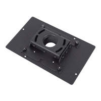
Component Storage Panel Installation
WARNING: Exceeding the weight capacity can result in
serious personal injury or damage to equipment! It is the
installer’s responsibility to make sure the combined weight of
all components attached to the component storage panel
cannot exceed 20 lbs (9.07 kg).
1. Install components to component storage panel (A) using
appropriate hardware (not included) for each component.
(See Figure 18)
2. Loosely install two 1/4-20 x 1/2" Phillips pan machine
screws (S) to either bottom upright (G) at desired mounting
location. (See Figure 18)
3. Use teardrop mounting holes to install component storage
panel (A) onto installed screws (S). (See Figure 18)
4. Tighten screws (S) to secure panel (A) to upright (G). (See
Figure 18)
Figure 18
(R) x 4
1
(T) x 4
RLF2
(B) x 2
(RLF2 shown)
1/2"
(R) x 4
2
(slotted washers) x 4
(B) x 2
LTM1U
(LTM1U shown)
1/2"
3
3
4
(A)
(S) x 2
4
(G)
2
3
3