AVSFSS Installation Instructions
6
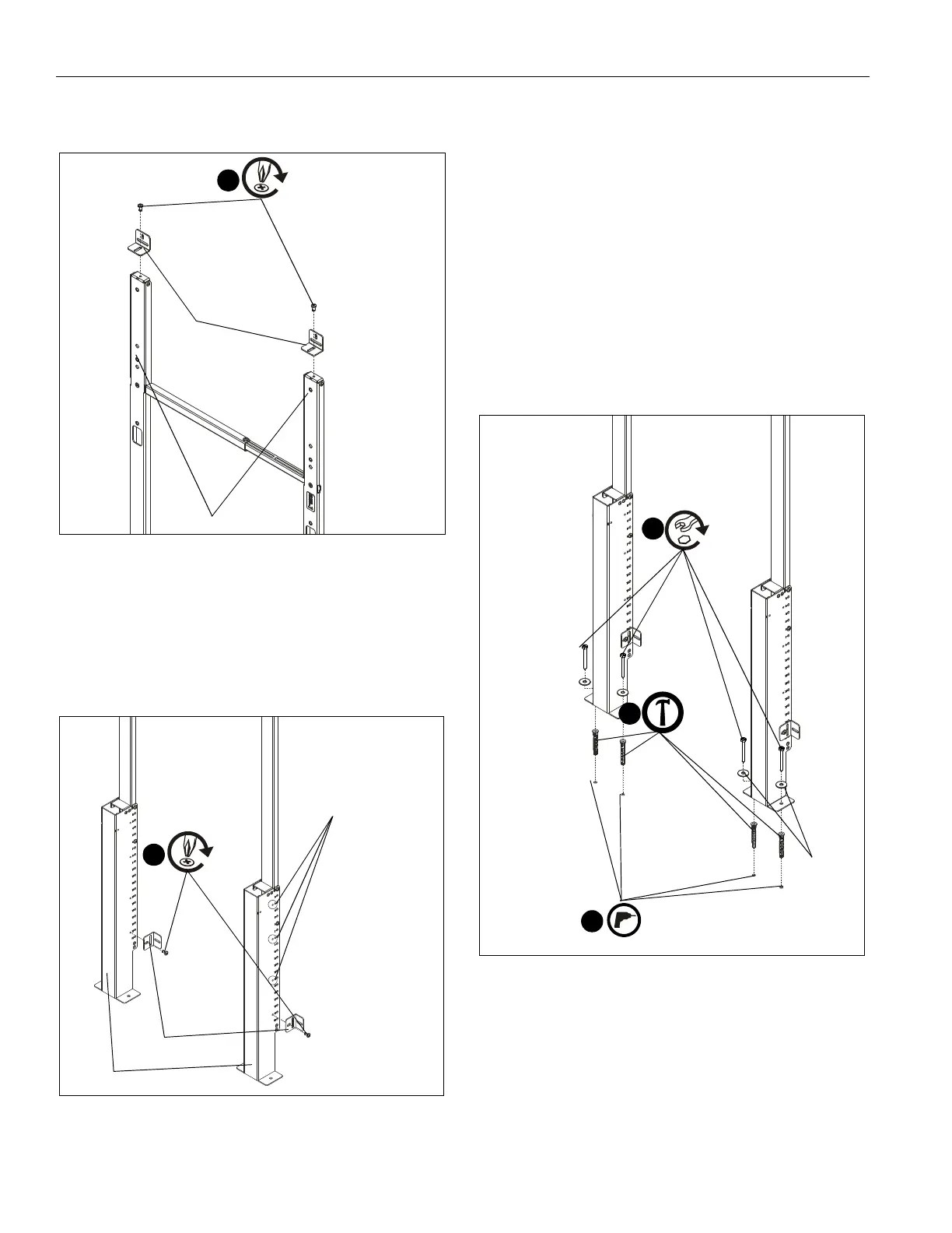
6. Use two 1/4-20 x 1/2" button head cap screws (S) to secure
two wall brackets (F) to top uprights (B). (See Figure 3)
Figure 3
7. Use two 1/4-20 x 1/2" button head cap screws (S) to secure
two wall brackets (F) to bottom uprights (G). (See Figure 4)
NOTE: Any of the four holes on each upright (G) can be used
on either side depending on where uprights were
attached to each other and/or component storage
panel location. (See Figure 4)
Figure 4
Attach to Concrete Floor (Optional)
IMPORTANT ! : AVSFSS may be bolted down to floor for
additional security and support. It may NOT be installed
to the floor ONLY without being also attached to the wall!
NOTE: If installing to floor, it is recommended to install to floor
BEFORE installing to wall or it will need to be
uninstalled from wall prior to floor installation.
1. Position assembled stand against wall at desired mounting
location and mark hole locations at each mounting location.
(See Figure 5)
2. Remove stand from location and drill 5/16" holes with a
depth of 2 3/8" (60mm) on marked hole locations. (See
Figure 5)
3. Use hammer to install four concrete anchors (Q) into drilled
holes. (See Figure 5)
Figure 5
4. Use four 1/4-20 x 2 1/2" hex head lag screws (M) and four
1/4" washers to secure wall brackets (F) to floor. (See
Figure 5)
6
(S) x 2
(F) x 2
(B) x 2
7
(S) x 2
(F) x 2
(G) x 2
other mounting holes
3/8"
2
(M) x 4
4
(Q) x 4
3
(N) x 4