Installation Instructions AVSFSS
9
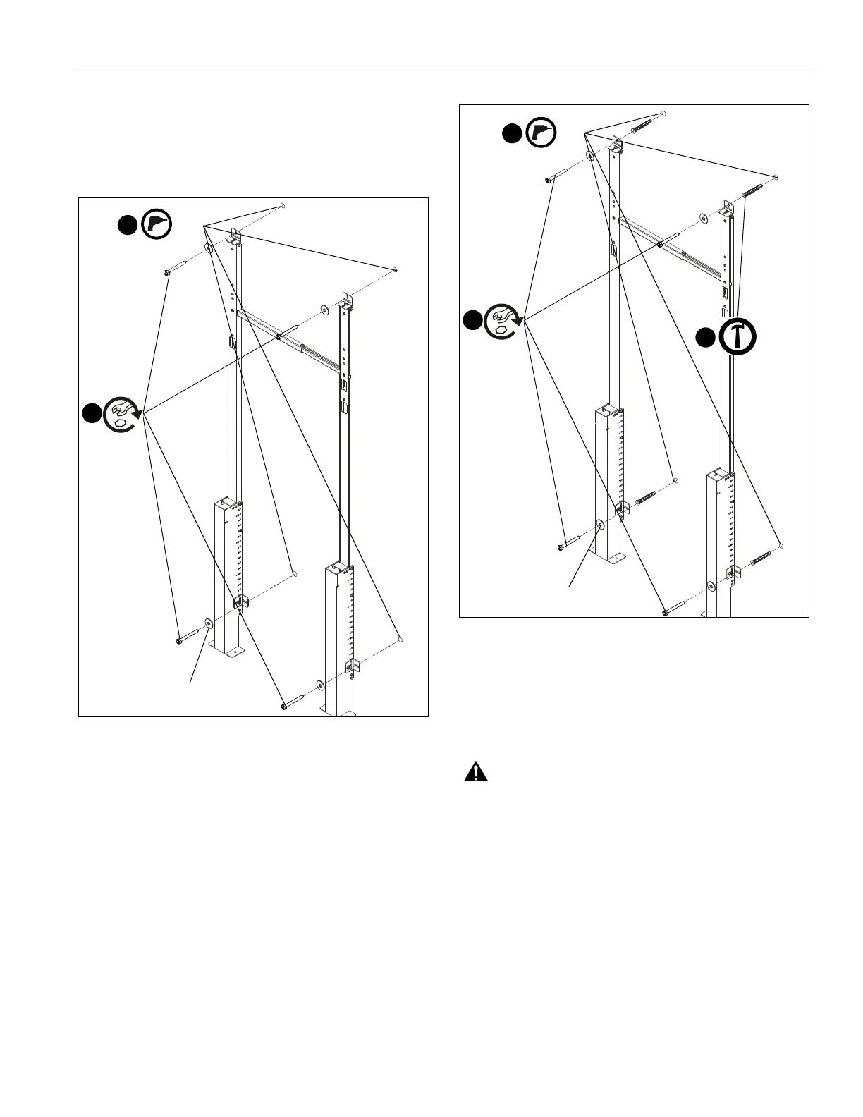
Drywall Installation (Into Wood Studs)
1. Mark hole locations at each mounting location based on
locations of wall brackets (F) and wood studs. Use a level to
ensure of an even mount. (See Figure 14)
2. Drill 1/8" holes on marked hole locations. (See Figure 14)
Figure 14
3. Use four 1/4-20 x 2 1/2" hex head lag screws (M) and four
1/4" washers (N) to secure wall brackets (F) to wall. (See
Figure 14)
Concrete Installation
1. Mark hole locations at each mounting location based on
locations of wall brackets (F). Use a level to ensure of an
even mount. (See Figure 15)
2. Drill 7/32" holes with a depth of 2 3/8" on marked hole
locations. (See Figure 15)
3. Use hammer to install four concrete anchors (Q) into drilled
holes. (See Figure 15)
Figure 15
4. Use four 1/4-20 x 2 1/2" hex head lag screws (M) and four
1/4" washers (N) to secure wall brackets (F) to wall. (See
Figure 15)
Display Installation
WARNING: Exceeding the weight capacity can result in
serious personal injury or damage to equipment! It is the
installer’s responsibility to make sure the combined weight of
all components and mounting systems attached to the top
uprights of the AVSFSS does not exceed 217 lbs (98.4 kg).
The combined weight of all components attached to the
mounting system being attached to the AVSFSS cannot
exceed the specific weight limit for that mounting system.
1/8"
2
(M) x 4
3
(N) x 4
7/16"
3/8"
2
(M) x 4
4
(Q) x 4
3
(N) x 4
7/16"