E3
Precautions during wiring
• Wiring operation should be done by professional
Wiring should be done by a person having actual experience and
basic knowledge of instrumentation.
• Mount the terminal cover
In order to ensure safety, after the wiring is done, take measures so
as to prevent direct contact with the terminal of the product. Exclusive
terminal cover of the instrument is available as accessory (Sold
separately).
• Keep away from strong power circuit and noise sources
In order to prevent adverse effect due to noise, do not place the
instrument near a device from which noise is generated (magnet
relay, motor, thyristor regulator, inverter etc.). Also avoid passing the
wiring of the instrument and that of noise generating devices through
the same duct. Always keep the wiring away from each other. Take
the necessary countermeasures against noise.
• Effect on measured values
If there is a possibility that the measured values are affected by the
above noise, high voltage, etc., check that the measured values are
normal using other measurement methods. Take measures if
necessary.
• Keep away from the heat generating sources
In order to prevent adverse effect due to high temperature, do not
place the instrument near the heat generating sources. If the
instrument is kept near any heat generating source, measurement
goes wrong and finally the life of the instrument is shortened. Pay
attention to the surrounding temperature of the instrument.
Avoid places where there is wind and sudden temperature change, it
also causes an error in measurement. Take necessary measures to
avoid such surrounding environment.
• Unused terminals
Do not connect anything to the unused terminal. Instrument may get
out of order.
• Countermeasures against erroneous output at the power ON
When power is ON, sometimes the output related signal may be
momentarily output when the instrument is starting normally.
Take necessary countermeasures by using an external circuit.
• About the devices and equipment connected to this device
Make sure that devices and equipment connected to this device have
reinforced insulation suitable for the maximum operating voltage of
this device's power supply and input/output ports.
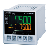
Insulation block
DB63
Power
terminals
Measuring input terminals
Remote input terminals R/L (analog) DI terminals
Control output 1 terminals
(current output type/SSR drive pulse output type/ voltage
output type)
Control output 1 terminals (ON-OFF pulse output type)
Event output 1/2 (mechanical relay output) terminals
Communications terminals R/L (digital) DI terminal
External signal input (DI1 to 5) terminals
*For "24V AC/DC", power terminals are at secondary side.
*Between control output 1 (ON-OFF pulse output type) and event
output 1/2 (mechanical relay output) is isolated.
DB65/67
Power
terminals
Measuring input terminals CT input terminals
Remote input terminals R/L (analog) DI terminals External
signal input (DI6/7) terminals
Control output 1/2 terminals
(current output type/SSR drive pulse output type/ voltage
output type)
ON-OFF servo (feedback input) terminals
Transmission output (4 to 20mA DC/0 to 10V DC)
Control output 1/2 terminals (ON-OFF pulse output type)
Event output 1 to 4 (mechanical relay output) terminals
ON-OFF servo (relay output) terminal
Communications terminals R/L (digital) DI terminal
External signal input (DI1 to 5) terminals
Event output 5 to 9 (open collector output )
*For "24V AC/DC", power terminals are at secondary side.
*Between control output 1/2 (ON-OFF pulse output type) and event
output 1 to4 (mechanical relay output) is isolated.
Basics of wiring
Refer to Instruction manual (General) 2-3-4 Basics of wiring for
connection to the terminal and about power supply terminal.
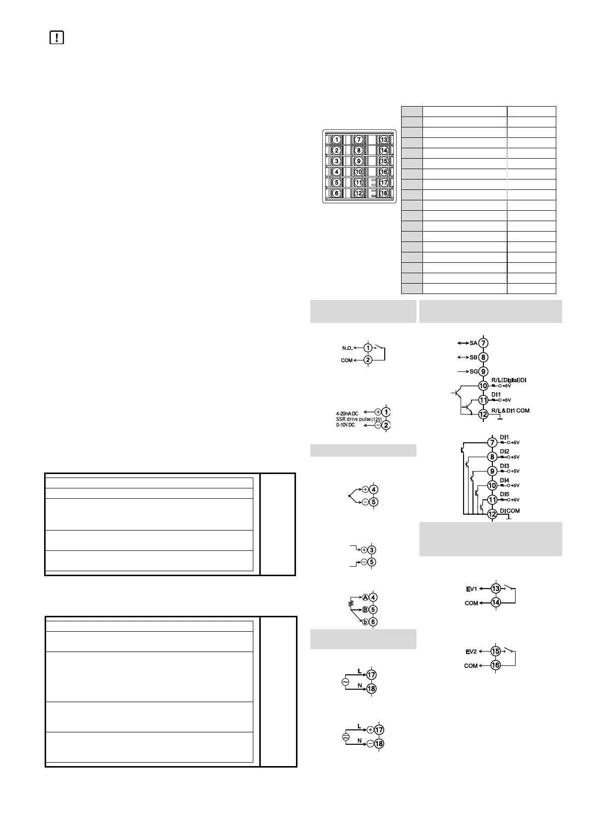
Wiring
DB63
(1) Control output 1 +
(2) Control output 1 -
(3) Measuring input +
(4) Measuring input + A
(5) Measuring input - B
(6) Measuring input b
(7) Communication SA DI1
(8) Communication SB DI2
(9) Communication SG DI3
(10) R/L (digital) DI4
(11) DI1 DI5
(12) R
/
L & DI COM DI COM
(13) EV1
(14) EV1 COM
(15) EV2
(16) EV2 COM
(17) Power L/+
(18) Power N/-
Control output 1 terminal
Communication interface /
external signal input terminal
ON-OFF pulse output RS485 + External signal input 1point
Current/SSR drive
pulse/voltage output
External signal input 5 points
Measuring input terminal
*1*2
Thermocouple/voltage mV
Voltage V (Current)
Event output terminal
(mechanical relay)
Event 1 output
Resistance thermometer
Event 2 output
Power terminal
100-240V AC Power
*1 Do not wire except for specified
terminals.
*2 For inputting current, connect shunt
resistor (250Ω/ EZ-RX250 sold
separately) between + and -.
24V AC/DC Power
 Loading...