NXMLE Series Residual Current Operated Circuit Breaker
06
5
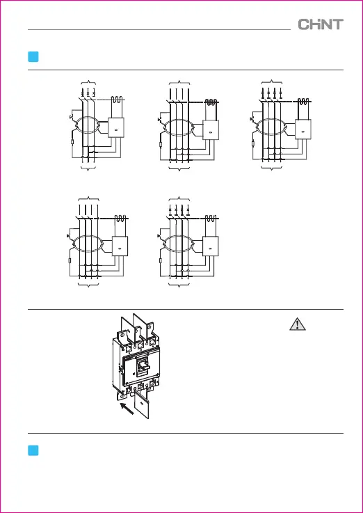
Leakage Wiring Diagram
LINE
SB
TA
RT
LOAD
IC
QI
1
3
5
N
2
4
6
N
LINE
SB
TA
RT
LOAD
IC
QI
2
4
6
N
1
3
5
N
SB:Test button
TA:Zero sequence current
Transformer
RT:Test resistance
IC:Integrated circuit
1P+N
2P
3P
3P+N 4P
Figure 12 Flash barrier
Insert in the direction of the
arrow on the flash barrier
①Be sure to install flash barriers
before product operation.
②Check if the wiring is correct.
③After installation ,the insulation
resistance to the ground shall
not be less than 10MΩ.
6
Environmental Protection
In order to protect the environment, the product or product parts should be disposed of according to
the industrial waste treatment process, or be sent to the recycling station for assortment, dismantling and
recycling.
LINE
SB
TA
RT
LOAD
IC
QI
2
4
6
N
1
3
5
N
LINE
SB
TA
RT
LOAD
IC
QI
1
3
5
2
4
6
LINE
SB
TA
RT
LOAD
IC
QI
1
3
5
N
2
4
6
N
 Loading...