Planning Model 108 FLEX-AUGER® Feed Delivery System
10
MA1714C
Model 108 Flex-Auger
®
Systems Bin Placement Chart
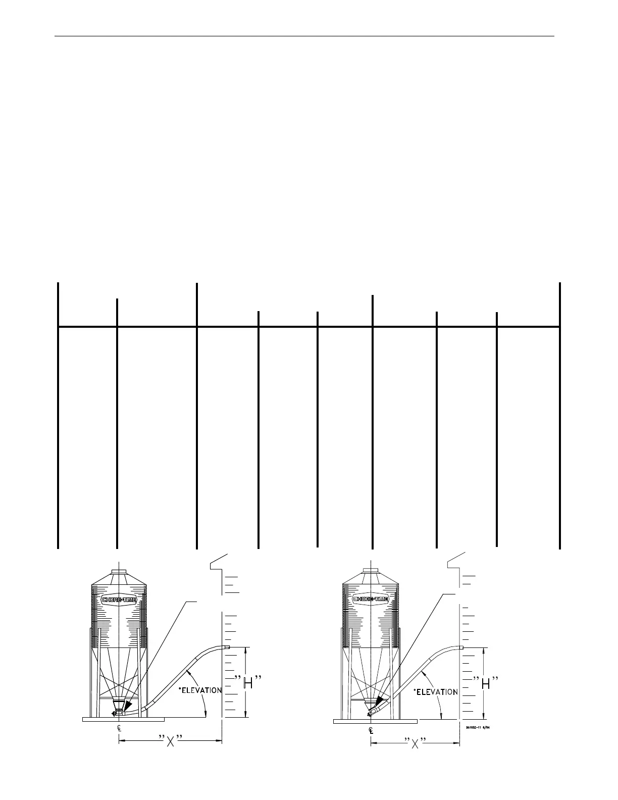
Use this chart to determine the distance from building to center of bin ("X") at the various entrance heights ("H")
and degrees of elevations listed below.
Degree of elevation = Angle at which the system is installed, including the 30 degree or straight-out Upper Boot.
These layout charts are for planning and reference purposes only. A combination of elbows and straight tube may
be required for your installation, depending on the distance from the bin to the building and the height at which
the auger tubes are to enter the building. The elbows may be easily cut to any angle required.
PAY PARTICULAR ATTENTION TO THE MINIMUM DISTANCE BETWEEN THE BIN AND THE
BUILDING.
Many installation and operational difficulties can be avoided if the bin is located farther from the building. If in
doubt, it is BETTER TO BE TOO FAR AWAY THAN TOO CLOSE.
The maximum recommended angle of elevation above the horizontal is 60 degrees. The maximum elevation is 30
feet (9.1 m) . . . if the angle of elevation is no more that 45 degrees.
All systems require adequate support of the auger tubes to prevent sagging and/or excessive forces being
transmitted to the bin boot.
Distance from Center of Bin to the Building "X"
System Model Entrance Height 30 Degree Upper Bin Boot (part no. 4347) Straight-Out Upper Bin Boot (part no. 6093)
"H" 30 Degree 45 Degree 60 Degree 30 Degree 45 Degree 60 Degree
Model 108 5’ (1.5 m) 9’ (2.7 m) - - - - - - - - - - - - 11.5’ (3.5 m) 10’ (3 m) - - - - - -
6’ (1.8 m) 11’ (3.4 m) 8.5’ (2.6 m) 8’ (2.4 m) 13.5’ (4.1 m) 11’ (3.4 m) 10’ (3 m)
7’ (2.1 m) 12.5’ (3.8 m) 9.5’ (2.9 m) 8.5’ (2.6 m) 15’ (4.6 m) 12’ (3.7 m) 11’ (3.4 m)
8’ (2.4 m) 14.5’ (4.4 m) 10.5’ (3.2 m) 9’ (2.7 m) 17’ (5.2 m) 13’ (4 m) 11.5’ (3.5 m)
9’ (2.7 m) 16’ (4.9 m) 11.5 (3.5 m) 9.5’ (2.9 m) 18.5’ (5.6 m) 14’ (4.3 m) 12’ (3.7 m)
10’ (3 m) 17.5’ (5.3 m) 12.5’ (3.8 m) 10’ (3 m) 20’ (6.1 m) 15’ (4.6 m) 12.5’ (3.8 m)
11’ (3.4 m) 19.5’ (5.9 m) 13.5’ (4.1 m) 10.5’ (3.2 m) 22’ (6.7 m) 16’ (4.9 m) 13’ (4 m)
12’ (3.7 m) 21’ (6.4 m) 14.5’ (4.4 m) 11.5’ (3.5 m) 23.5’ (7.2 m) 17’ (5.2 m) 13.5’ (4.1 m)
13’ (4 m) 23’ (7 m) 15.5’ (4.7 m) 12’ (3.7 m) 25.5’ (7.8 m) 18’ (5.5 m) 14’ (4.3 m)
14’ (4.3 m) 24.5’ (7.5 m) 16.5’ (5 m) 12.5’ (3.8 m) 27’ (8.2 m) 19’ (5.8 m) 15’ (4.6 m)
15’ (4.6 m) 26.5’ (8.1 m) 17.5’ (5.3 m) 13’ (4 m) 29’ (8.8 m) 20’ (6.1 m) 15.5’ (4.7 m)
16’ (4.9 m) 28’ (8.5 m) 18.5’ (5.6 m) 13.5’ (4.1 m) 30.5’ (9.3 m) 21’ (6.4 m) 16’ (4.9 m)
17’ (5.2 m) 30’ (9.1 m) 19.5’ (5.9 m) 14’ (4.3 m) 32.5’ (9.9 m) 22’ (6.7 m) 16.5’ (5 m)
18’ (5.5 m) 31.5’ (9.6 m) 20.5’ (6.2 m) 14.5’ (4.4 m) 34’ (10.4 m) 23’ (7 m) 17’ (5.2 m)
19’ (5.8 m) 33.5’ (10.2 m) 21.5’ (6.5 m) 15.5’ (4.7 m) 36’ (11 m) 24’ (7.3 m) 17.5’(5.3 m)
20’ (6.1 m) 35’ (10.7 m) 22.5’ (6.8 m) 16’ (4.9 m) 37.5’ (11.4 m) 25’ (7.6 m) 18.5 (5.6 m)
Straight-out Boot
30 Degree Boot