Installation
2.4 Output Connection
Output power can be connected from the terminal block located at the rear panel of the
instrument through terminals L and N to the load. Besides, it can be connected from the
universal receptacle located at the front panel using power cord to the load. To satisfy
safety requirements, the wires to the load should be of a sufficiently large gauge to insure
they do not overheat while carrying the output current. Refer to Figure 2-2 and Figure 2-3.
2.5 Remote Sense Connection
The remote sensing connections improves the voltage regulation at the load by monitoring
the voltage there instead of at the AC source output terminal. Remote Sensing allows the
power supply to automatically increase the output voltage and compensate the voltage
drops in the load leads. Note that with remote sensing, voltage read-back is at the load.
Connect the unit for remote voltage sensing by connecting load leads from the output
terminals to the load, and the sensing leads from the S
L
and S
N
terminals to the load as
shown in Figure 2-3.
2.6 Power-on Procedure
Apply the line power and turn on the front panel power switch. No loads should be
connected to the output terminal block. The instrument performs a series of self-tests each
time when turning on the power-switch. All front panel LEDs, including alphanumeric and
indicator LEDs, are turned on and holds about 3 seconds. Then, the seven segment LEDs,
alphanumeric LEDs will show “SELF TEST” indicating that the 6404/6408 is running self-
test routines.
Then, the seven segment LEDs display model number (6404 or 6408), firmware version
number (e.g. “ver 1.2”) as below:
If any error is detected during the self-test routine, an error message will be displayed on
the LED. For example,
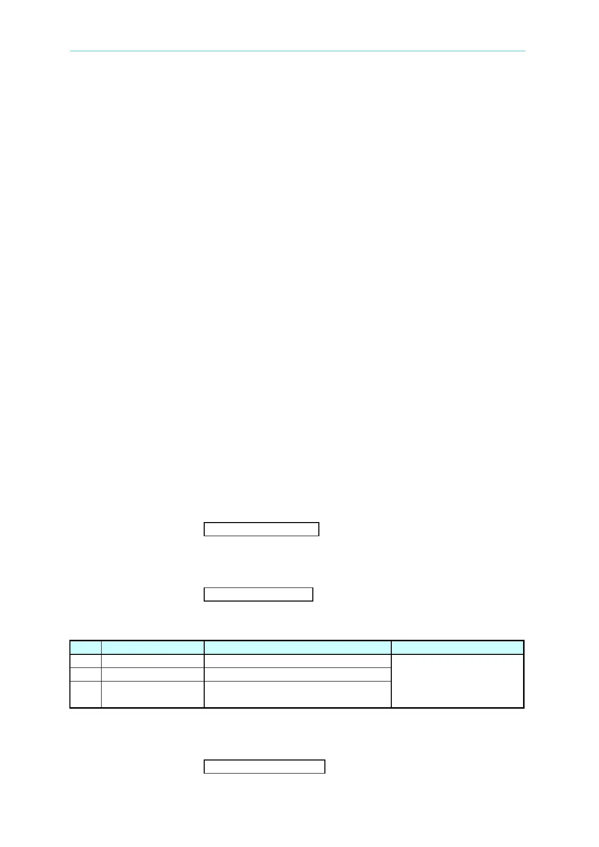
The following table shows all the error messages and recommended actions:
System memory test failure.
for assistance in case of
self-test failure.
System EEPROM tests failure.
CPU and DSP communication test
failure.
After the self-test routines are completed the LEDs turn to show the current setting values of
V and F, and measured value of I, indicating the 6404/6408 is ready for use as below: