Programmable AC Source 6404/6408 User’s Manual
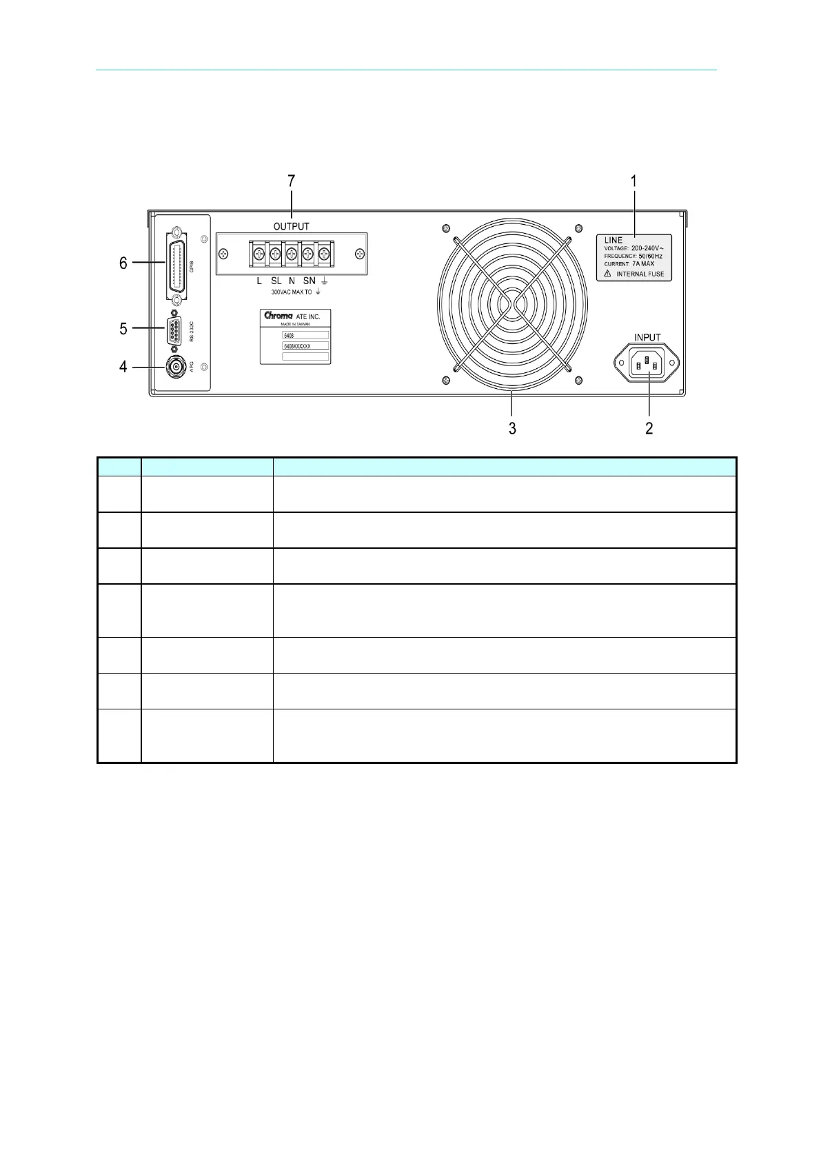
1.4.2 Rear Panel
The model number 6404 or 6408 and power line input ratings are
marked on the label.
Power Line Input
Connector
Power line input is connected to the 6404/6408 through this
connector.
Cooling fan speed automatically increases or decreases as
temperature rises or falls.
Control the output Vrms of the 6404/6408 by using external DC
voltage level. Such signal is input through this BNC connector. This
connector is on the same optional board as items 5 and 6.
This port located on the same GPIB optional board offers
alternative interface to the 6404/6408 for remote operation.
The optional interface provided by the 6404/6408 for
communication with the remote GPIB controller.
Output Connector
Output power can be connected from the terminal block located at
the rear panel of the instrument through terminals L and N to the
Table 1-2 Rear Panel Description