Programmable AC Source 6404/6408 User’s Manual
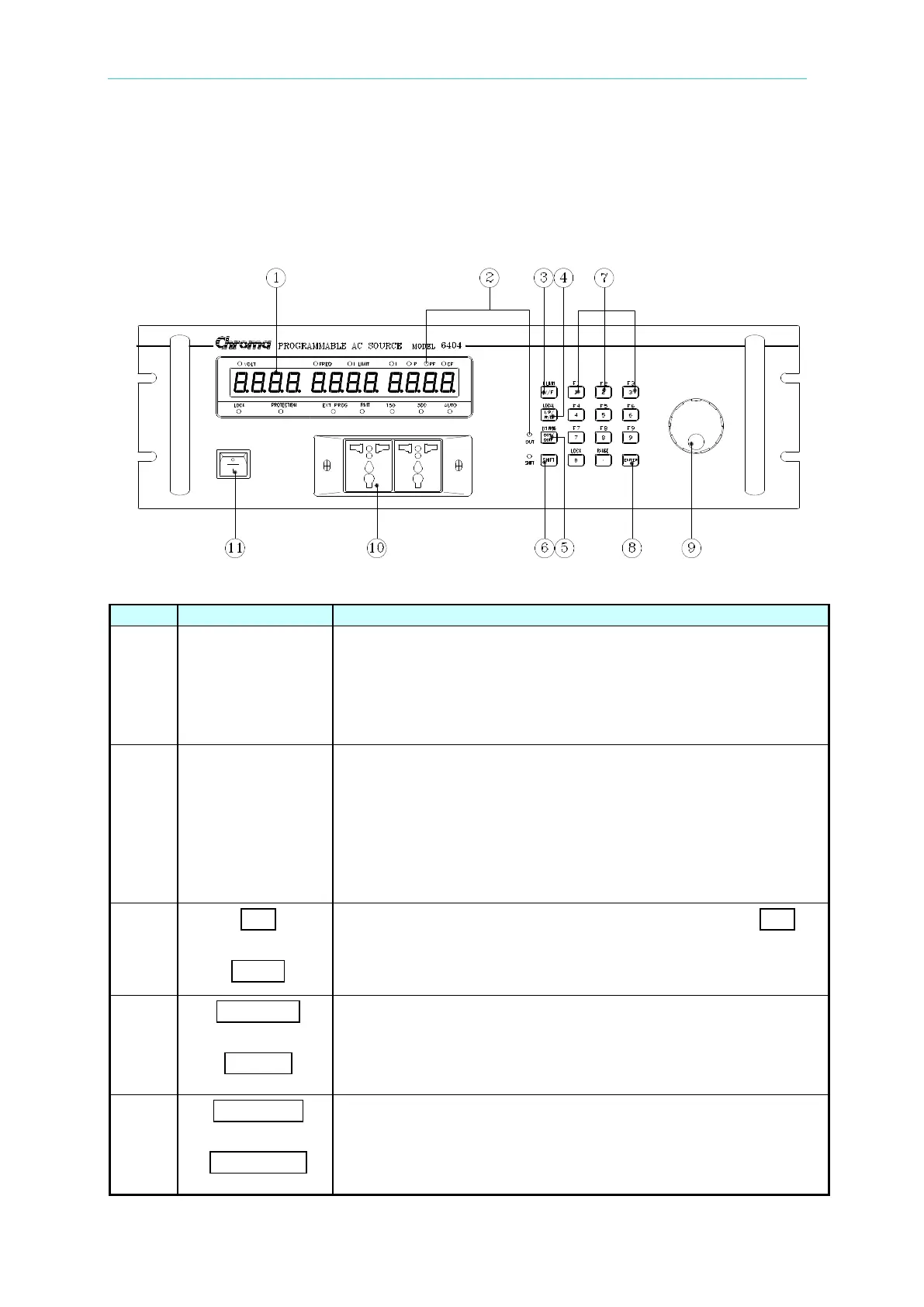
1.4 Operational Panels
1.4.1 Front Panel
Alphanumeric LED: A row of red seven-segment LEDs are
equipped for displaying setup messages and numeric value of
settings or measurement results. The display area is divided
into three sections; value of V shows at the left, frequency or I
limit, at the middle, and any of I/P/PF/CF measurement value,
2
Indicator LED: LEDs located on the upper and lower part of
the display panel are the indicators for showing the status
being activated. These indicators include “VOLT”, “FREQ”, “I
LIMIT”, “I”, “P”, “PF”, “CF”, “LOCK”, “PROTECTION”, “EXT
PROG”, “RMT”, “150V”, “300V”, “AUTO”.
Besides, two LEDs, “OUT” and “SHIFT”, for showing activation
of output and shift mode, are available which are located on
the keypad area next to the corresponding keys.
3
V/F
-------- or --------
I limit
V/F or I limit selection key: Under normal mode, the V/F
key offers the user selection of programming on voltage or
frequency. Under shift mode, this key enables the user to
program software limit for current (I limit).
4
I/P/PF/CF
-------- or ---------
LOCAL
I/P/PF/CF selection key: Under normal mode, the user can
repeatedly press this key to select one of the measurement
values to be displayed. Under shift mode, this key provides the
user for returning controls from remote PC to front panel
5
OUT/QUIT
-------- or ---------
EXT PROG
OUT/QUIT command key: Under normal operation, presses of
this key may enable the 6404/6408 outputs power to the
loading devices. If the user enters setup procedures, this key is
used to quit from current setting routine. Under shift mode, this
key enables external programming.