Programmable AC Source 6404/6408 User’s Manual
O Board
I Board
EMI Filter
Power
Stage
Power
Supply
Input
Power
P Board
Power Stage
FAN speed
control
B Board
A Board D Board
Optional Board K Board
Seven-Segment
LED Display
Key
IEEE-488
Port
RS-232
Port
External
V Port
Vmeas.
Imeas.
+5V
+15V
-15V
control
Data &
Control bus
Data &
Control bus
VextGPIB RS-232C
+5V
Output
Power
FAN
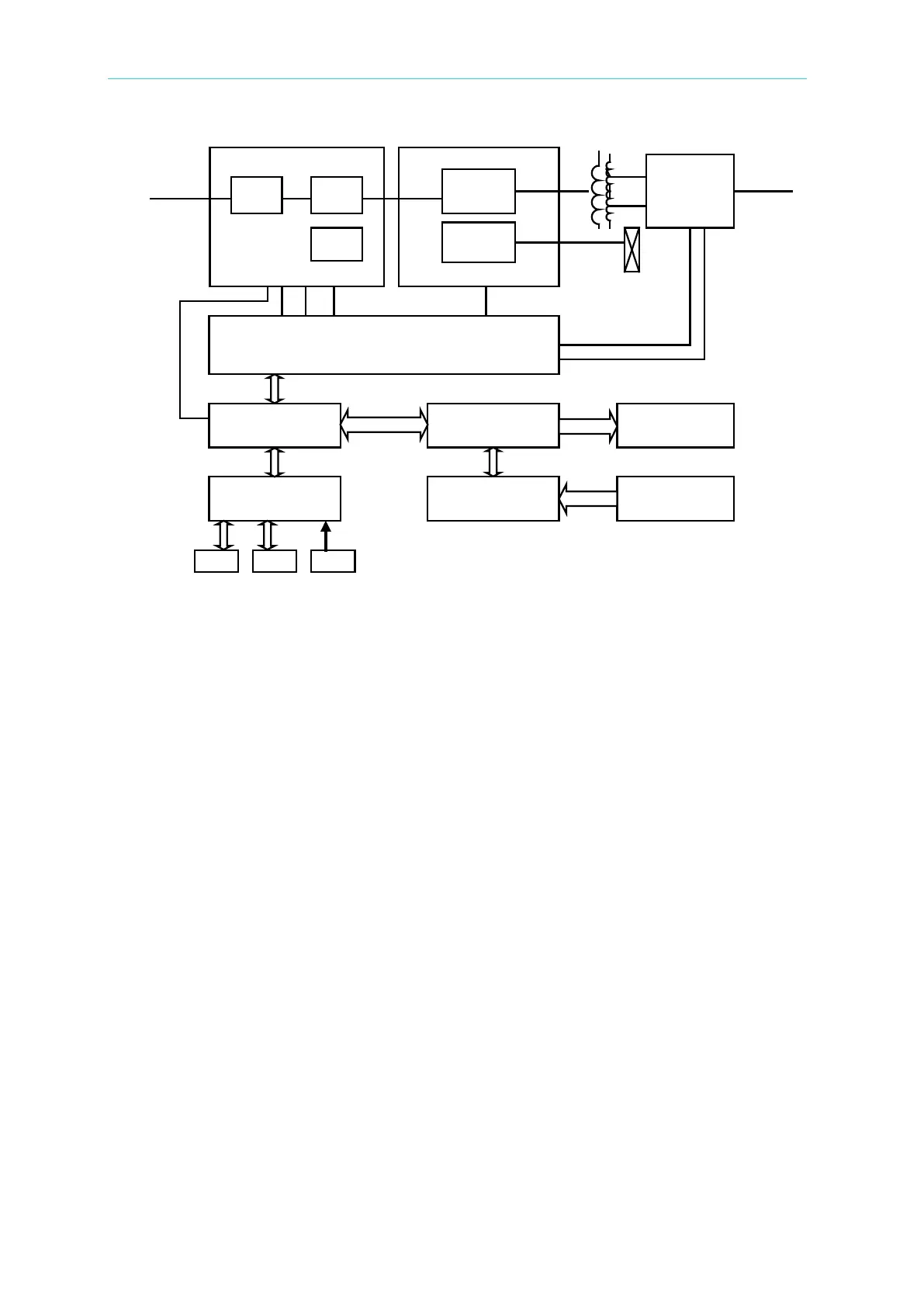
Figure 4-1 System Block Diagram
4.3 AC/DC Power Stage Converter
This assembly is identified as I board. It generates the high voltage Vdc supply. This power
stage also includes power supply circuits that generate the DC voltage identified as +15V, -
15V, and +5V. Power factor correction technology for 6408 is used to achieve a power
factor of 0.98 or more.
4.4 DC/AC Inverter
This assembly comprises of control part at B board, P board, output transformer, and O
board. It generates an AC output sine wave.
Advanced PWM technology is applied to this system to obtain more stability. Maximum
peak current is clamped to protect output power MOSFET. Overload protection (OLP),
which contains output protection against short circuit, is also implemented here.
P board is made up of the full bridge of MOSFET power components. The PWM control
signal from controller is applied to the full bridge to amplify the output. The low pass filter
can reject the switching frequency component.
O board consists of the range relays and output relays. Output relays can isolate the AC
source from the external source when any error occurs. Range relays connect the tow sets
of the secondary of output transformer together in parallel or serial.