9
Security Codes and Levels
To limit access to the user configuration interface,
security codes are assigned to different menu levels.
Make security codes available to operators, mainte-
nance crew, supervisors, etc. according to what func-
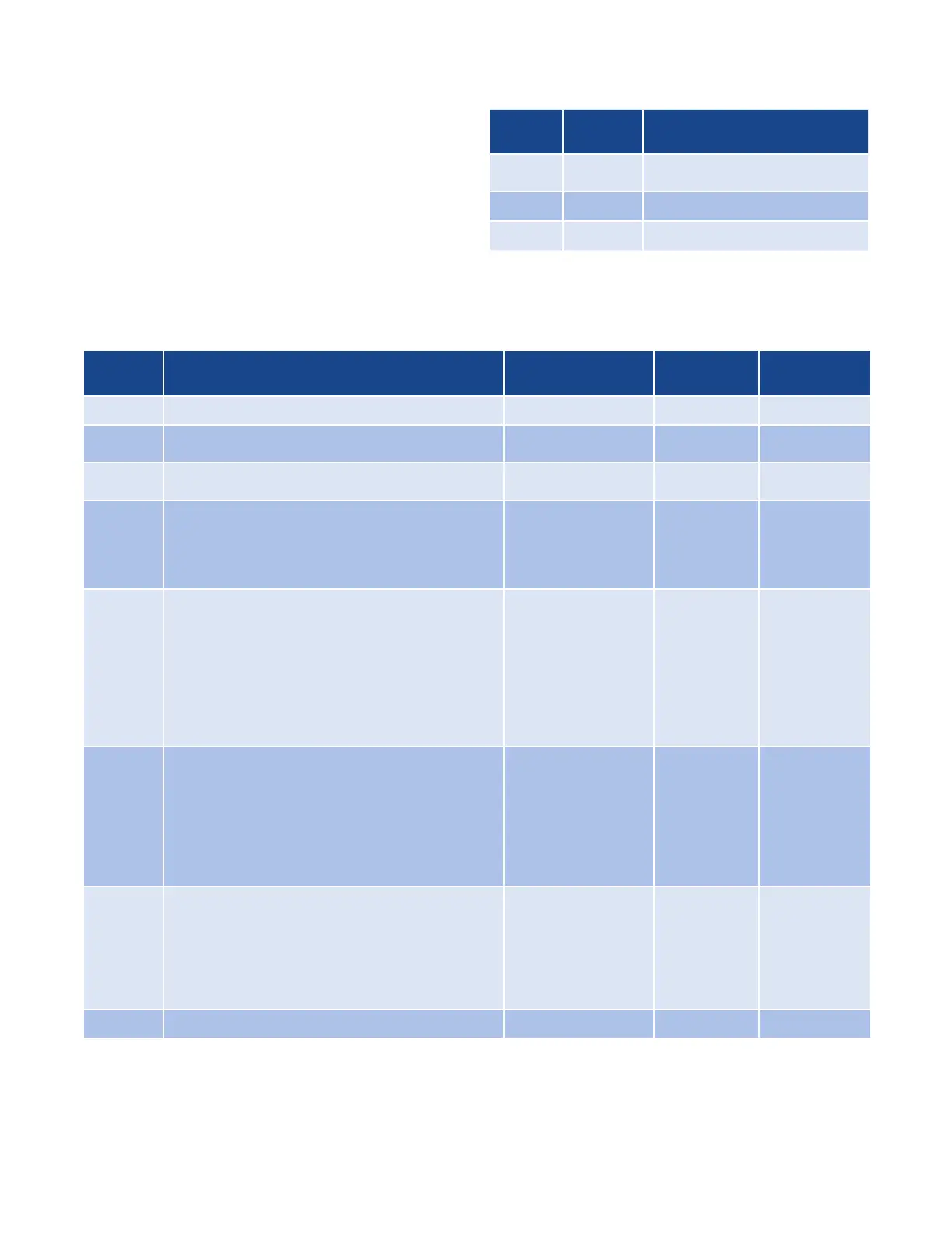
tion level you want for each group. Security Level C
is not recommended for most users. Gain access to
configuration menus using the following codes.
Security
Level
Security
Code Function
A All Values
Allows adjustment of the
Set Point
B 458 Basic Menus
C 736 Calibration Menus
Configuration Menus
The following configuration menus can be accessed through the user interface (see Configuration, page 12).
Menu
Code Function Adjustable Range
Factory
Default
Security
Level
Loch Security Lock 0-999 458 A
Proc
Process Variable Display Displays the actual
process temperature.
Read Only °F or °C N/A A
SP
Process Set Point Adjust Adjusts the target
process temperature.
Sensor Range °F
or °C
0°F A
Pb
Proportional Band Temperature range above/
below set point where proportional control
is active. Most applications require a band
between 10 to 200°F. This menu is active only
when the dip switch is set to “PI”
1 to Sensor Span
Maximum °F or °C
25 B
ArSt
Automatic Reset Control feature that automati-
cally corrects for small temperature offsets that
occur in proportional control. The higher the
setting, the faster the correction occurs. A high
setting could cause overshoot during start-up.
A low setting will not allow process temperature
to reach to set point quickly enough. A setting
of “0” turns off automatic reset. This menu is
active only when the dip switch is set to “PI”.
0.0 to 100.0
Repeats/ Min.
0.1
CYCL
Cycle Time The time for the output to com-
plete ON to OFF to ON cycle. Used only with
proportional control. A fast cycle time provides
better control, but can cause premature wear
to contactor or other power switching devices.
Magnetic contactors should not be switched at
less than a 30 second cycle time. This menu is
active when the dip switch is set to “PI”.
.1 to 60.0 Sec.
Output R1,
R3 = 30 sec.
S0, S1, S2,
V0 = 1 sec.
B
db
On/Off Dead Band The range above/below set
point in which no control action takes place.
Determines at what temperature the output
switches ON and OFF. For a 5°F dead band,
2.5°F is above and below the set point. This
menu is active when the dip switch is set to
“ONOF”.
1 to 100 °F or °C 5 Foc B
ALty Alarm Type Select high or low alarm. Off, Hi or Lo OFF B

 Loading...

