1
1. Quick Setup
After the controller is properly wired into the system,
the user only needs to verify the sensor input and con-
trol type and adjust the set point.
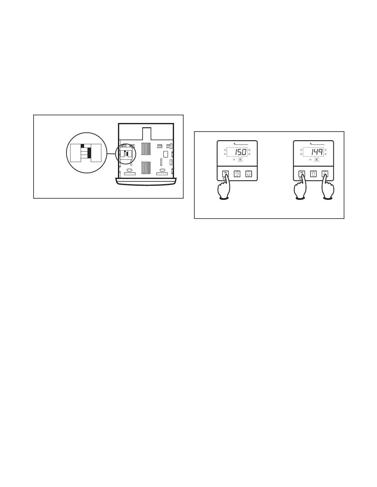
Setting the Sensor and Control Mode
Adjust the dip switches located on the bottom of the
unit as shown in Figure 1.1. The factory settings are J,
TC, °F, and PI. It is simpler to adjust the dip switch prior
to mounting the 2110.
Figure 1.1
Dip Switch Settings
J
RTD
˚C
ONOF
K
TC
˚F
PI
J
RTD
˚C
ONOF
K
TC
˚F
PI
Adjusting the Set Point
1. Apply power to the unit.
2. To adjust the set point on the Chromalox 2110 Tem-
perature Controller, press and hold the Set Point
button (see Figure 1.2). The Set Point light is illumi-
nated.
3. While still pressing the Set Point button, press either
the
d
or
f
button to adjust the set point to the de-
sired value (see Figure 1.3). Holding the
d
or
f
but-
ton increases the speed of the set point changes.
Figure 1.2
Establishing the Set Point
Figure 1.3
Adjusting the Set Point
Load
Alarm
°F
°C
Temp
Point
Set Point
Chromalox 2110
Load
Alarm
°F
°C
Temp
Point
Set Point
Chromalox 2110
The Controller is now operational with factory settings.
For more precise control, set up of the alarm, etc., see
Section 4 – Adjusting Set Point and Configuration.

 Loading...