6
Sensor Input Wiring
For safety and best controller performance,
• Sensor leads (thermocouple and RTD) should not
be run in the same conduit as power wiring.
• Twisted pair, shielded wire is recommended for sen-
sor connections.
• False temperature readings can occur if the sensor
wire is exposed to electrical noise.
• Ungrounded thermocouples are recommended.
• Thermocouple extension wire, if required, must be
the same type as the thermocouple (i.e. if a Type K
thermocouple is used, then Type K extension wire
must be used.)
• Shielded thermocouple wire, if used, must have the
shield grounded at one end only, preferably at the
shield ground terminal on the controller as shown in
Figure 3.6.
• Three-wire RTDs are recommended for greatest ac-
curacy.
• Standard shielded copper wire is recommended for
RTD extensions.
Thermocouple Inputs
It is important to observe polarity (+,-) when connect-
ing thermocouple leadwires. ANSI color coding for the
thermocouples used with this instrument are
Thermocouple
Type
Material
Polarity
(+)
Polarity
(-)
J iron/constantan white red
K chromel/alumel yellow red
Make thermocouple wiring connections to terminals as
shown in Figure 3.6.
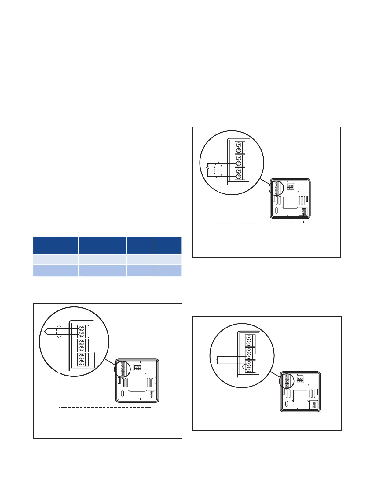
Figure 3.6
Thermocouple Connections with Shield
TC -
NC
NO
COM
TC +
Shield
Ground
Three-Wire RTD Inputs
IMPORTANT: When making the three-wire RTD
input connection, make the resistance of all
three extension leadwires equal by using the
same gauge and same length of wire for opti-
mum accuracy.
A three-wire RTD will generally have two wires of the
same color. Connect the same colored wires to the
RTDL connections. Connect the alternate colored wire
to the RTDH connection.
Make three-wire RTD connections to terminals as
shown in Figure 3.7.
Figure 3.7
Three-Wire RTD Connections with Shield
RTDL
RTDH
RTDL
NC
NO
COM
Shield
Ground
Two-Wire RTD Inputs
If using a two-wire RTD input, use heavier gauge lead-
wires to reduce leadwire resistance. Any leadwire re-
sistance adds directly to sensor resistance, thus add-
ing error to the process temperature measurement. It
is also necessary to jumper the two RTDL terminals on
the instrument to complete a two-wire hookup.
Figure 3.8
Two-Wire RTD Connections
NC
NO
COM
RTDL
RTDH
RTDL

 Loading...