27
6040, 8040 & 4040 Controllers -
Operator Mode
This is the mode used during normal operation of the
instrument. It can be accessed from Select Mode, and
is the usual mode entered at power-up. The available
displays are dependent upon whether Dual or Remote
Setpoint modes are being used, whether Setpoint
Ramping is enabled and the setting of the Display
Strategy parameter in Configuration Mode.
IN NORMAL OPERATION, THE OPERATOR MUST
NOT REMOVE THE CONTROLLER FROM ITS
HOUSING OR HAVE UNRESTRICTED ACCESS
TO THE REAR TERMINALS, AS THIS WOULD
PROVIDE POTENTIAL CONTACT WITH HAZARD-
OUS LIVE PARTS.
Set all Configuration Mode parameters and Set
Up Mode parameters as required before start-
ing normal operations.
6040, 8040 & 4040 Controllers –
Extended Operator Mode
Using the PC configuration software, it is possible to
extend the Operator Mode displays available by add-
ing parameters from Setup Mode. When an extended
Operator Mode is configured the additional parameters
are available after the standard operator displays.
Navigating in Operator Mode
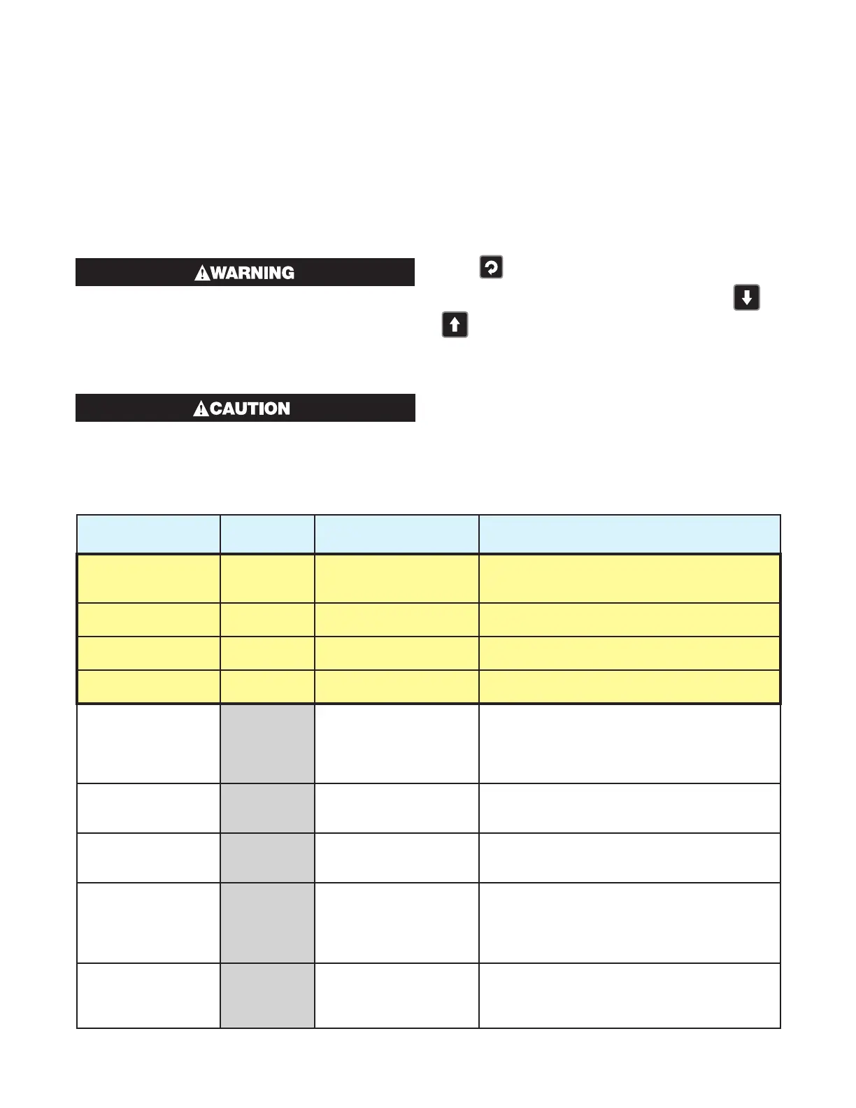
Press to move between displays.
When a display value can be adjusted, use
or
to change its value.
Note: The operator can freely view the parameters in
this mode, but alteration depends on the settings in
the Configuration and Set Up Modes. All parameters
in Display strategy 6 are read only, and can only be
adjusted via Setup mode.
Table 13. 6040, 8040 & 4040 Operator Mode Displays
Upper
Display
Lower
Display
When
Visible Description
PV Value Active SP
Value
Display strategy 1 and 2.
(Initial Screen)
Process Variable and target value of currently
selected Setpoint.
Local SP is adjustable in Strategy 2
PV Value Actual SP
Value
Display strategy 3 and 6
(Initial Screen)
Process Variable and actual value of selected
Setpoint (e.g. ramping SP value). Read only
PV Value Blank Display strategy 4
(Initial Screen)
Shows Process Variable.
Read only
Actual SP Value Blank Display strategy 5
(Initial Screen)
Shows target value of currently selected Set-
point. Read only
SP Value
SP
Display strategy 1, 3, 4,
5 and 6 if Digital Input
is not diS1 in config
mode and RSP is not
fitted
Target value of Setpoint.
Adjustable except in Strategy 6
SP1 Value
SP1 or
-
SP1
If Digital Input is set for
dual SP (diS1 in config
mode).
Target value of Setpoint 1.
-
SP1 means SP1 is
selected as the active Setpoint.
Adjustable except in Strategy 6
SP2 Value
SP2 or
-
SP2
If Digital Input is set for
dual SP (diS1 in config
mode).
Target value of Setpoint 2.
-
SP2 means SP2 is
selected as the active Setpoint.
Adjustable except in Strategy 6
Local Setpoint Value
LSP
-
LSP
or LSP
If Remote Setpoint Input
is fitted and Digital Input
is not diS1 in config
mode
Target value of Local Setpoint.
-
LSP means
the local setpoint is selected as the active SP
(if the digital input has been overridden, the
-
character is lit instead).
Adjustable except in Strategy 6
Remote Setpoint
Value
rSP
-
rSP
or rSP
If Remote Setpoint Input
is fitted and Digital Input
is not diS1 in config
mode
Target value of Remote Setpoint.
-
rSP means
the remote setpoint is selected as the active
SP (if the digital input has been overridden, the
-
character is lit instead). Read Only

 Loading...

